High speed ceiling nail having gunpowder

A technology of ceiling nails and gunpowder, applied in nailing tools, manufacturing tools, etc., can solve problems such as poor support effect, low efficiency of operation mode, and misoperation, so as to simplify ceiling operation, improve operation efficiency, and prevent misoperation Effect

Inactive Publication Date: 2017-05-31
PREGUN IND
View PDF10 Cites 2 Cited by
  • Summary
  • Abstract
  • Description
  • Claims
  • Application Information

AI Technical Summary

Problems solved by technology

This gunpowder nail 5 utilizes a gunpowder actuating tool to fire, and the Z-shaped fixing piece 6 must be connected with the gunpowder nail 5 before firing, so the efficiency of this operation method is relatively low, and the Z-shaped fixing piece 6 is easy to fire. Straightened and poorly supported
[0004] Patent No. CN104690690A discloses a gunpowder nail, which includes a main body, propellant powder, primer powder, and a protective layer coated on the outside of the propellant powder and primer powder. Although the protective layer can achieve the purpose of moisture resistance and the effect of stable firing , but the end faces of the firing powder and the primer protrude from the end face of the main body. When an external force breaks through the protective layer and hits the primer, there is a danger of malfunction. Moreover, this gunpowder nail is also used to cooperate with the fixed piece. , it is also necessary to connect the fixed piece with the gunpowder nail before firing, and there are still problems of low operating efficiency and poor supporting effect

Method used


Image

  • High speed ceiling nail having gunpowder
  • High speed ceiling nail having gunpowder
  • High speed ceiling nail having gunpowder

Examples


Embodiment Construction

[0013] The invention will be further described below by means of drawings and specific embodiments. The specific embodiments described here are only for explaining the invention, and are not intended to limit the protection scope of the present invention.

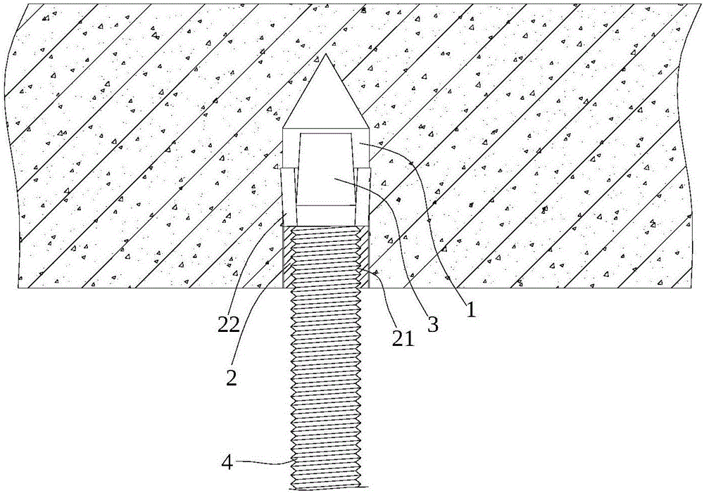
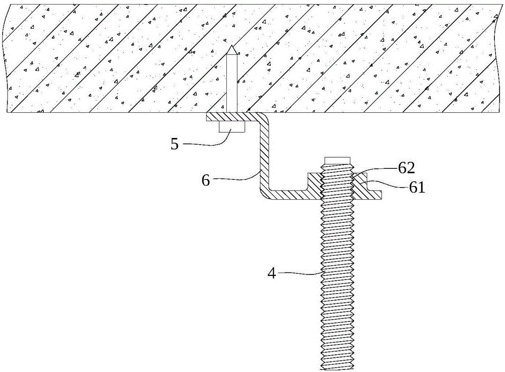
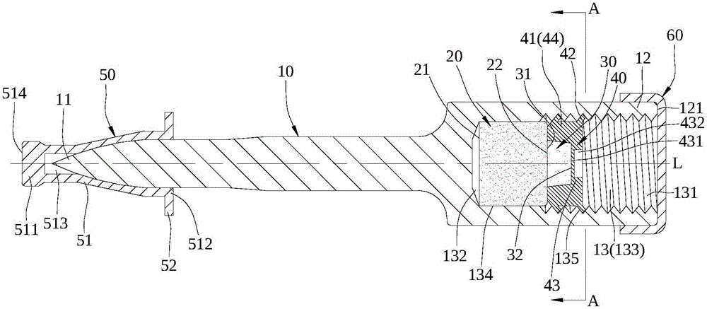
[0014] High-speed ceiling nails with gunpowder, such as Figure 3 ~ Figure 5 As shown, it includes a body 10 , propellant powder 20 , primer powder 30 , primer seat 40 , shield 50 and cover 60 .

[0015] The main body 10 extends along the central axis L and is in the shape of a stepped rod. One end of the main body 10 is the firing tip 11, and the other end is the impacted part 12. The impacted part 12 has an end surface that is opposite to the firing tip 11 and perpendicular to the central axis L. 121, the impacted portion 12 has an accommodating chamber 13 recessed toward the firing tip 11, the accommodating chamber 13 has an open end 131 adjacent to the end face 121 and a bottom end 132 opposite to the open end 131, the...


PUM

PropertyMeasurementUnit
Thicknessaaaaaaaaaa

Abstract

A high speed ceiling nail having gunpowder comprises a body, emission gunpowder, base gunpowder and a base gunpowder seat. The body comprises a firing tip and an impact bearing part which is equipped with an accommodating chamber comprising an opening end and a base end. The inner wall of the accommodating chamber is near the opening end and comprises an inner thread. The emission gunpowder is installed in the accommodating chamber and the base gunpowder is also installed in the accommodating chamber and in contact with the outer side end of the emission gunpowder. The base gunpowder seat is fixedly arranged in the accommodating chamber and covers the bottom of the base gunpowder. According to the invention, the base gunpowder seat is fixedly arranged in the accommodating chamber and covers the outer side of the base gunpowder, so objectives of moisture prevention and avoiding of mistaken behaviors are achieved; and when the body suffers impacts to be fixed to the wall face, threaded connection with a ceiling piece can be performed through the inner thread of the accommodating chamber, so an objective of convenient and quick assembly is achieved.

Description

technical field [0001] The invention relates to a building fixture, in particular to a high-speed ceiling nail with gunpowder. Background technique [0002] When setting up suspended ceiling objects on buildings or decorations, it is necessary to fix the hanging seat with nails on the wall. The traditional operation method, one of which is as figure 1 As shown, a fixing hole 1 is first drilled on the top of the building, and an expansion bolt 2 is fixed in the fixing hole 1. The bottom end of the expansion bolt 2 has an internal thread 21, and four slots 22 are arranged on the peripheral wall of the top end. , and then insert a truncated cone-shaped support block 3 into the expansion bolt 2 according to the way that the top is small and the bottom is large, so that the top of the expansion bolt 2 is stretched and squeezed into the building, and finally the ceiling piece 4 is installed into the expansion bolt 2 Among them, the ceiling member 4 is screwed with the expansion b...

Claims


Application Information

Patent Timeline
IPC IPC(8): B25C1/12
CPCB25C1/126
Inventor 杨文章
Owner PREGUN IND
Why Eureka
Try Eureka