
Dedicated guide device for manufacturing concrete block

A technology of concrete blocks and guide devices, which is applied in the direction of manufacturing tools, auxiliary molding equipment, ceramic molding machines, etc., can solve the problem of inability to ensure that the left and right ends of the upper clamp blank frame move upwards synchronously, the block rejection rate increases, and the production increase To meet the needs of modern production, reduce the scrap rate and avoid damage

Inactive Publication Date: 2017-05-31
谢晶晶
View PDF0 Cites 2 Cited by
  • Summary
  • Abstract
  • Description
  • Claims
  • Application Information

AI Technical Summary

Problems solved by technology

[0002] With the existing aerated concrete block breaking trigger, when the upper and lower clamping frames are separated by breaking the aerated concrete block and moving up and down, it cannot be guaranteed that the left and right ends of the upper clamping frame move upwards synchronously, which will cause being broken The blocks of the pulley are partially damaged due to torsion, which leads to an increase in the reject rate of the blocks and increases the production cost

Method used


Image

  • Dedicated guide device for manufacturing concrete block

Examples


Embodiment 1

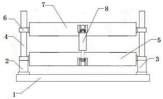
[0013] This embodiment provides a special guiding device for concrete block manufacturing, which is characterized in that: the special guiding device for concrete block manufacturing includes a base (1), a left driving cylinder (2), a right driving cylinder (3), a wire Bar (4), lower clamp blank frame (5), nut (6), upper clamp blank frame (7), jacking cylinder (8);

[0014] Among them: including the base (1), the left drive cylinder (2) and the right drive cylinder (3) are arranged on the left and right sides of the base (1), and the screw rods ( 4), the two ends of the lower clamp blank frame (5) are fixed on the cylinder body of the left and right drive cylinders (2, 3), and the left and right ends of the upper clamp blank frame (7) are adapted to the threads of the lead screw (4) by installing The nut (6) is sleeved on the lead screw (4) on the left and right sides, and the nut (6) is movably connected to the upper blank frame (7), between the upper blank frame (7) and the ...

Embodiment 2

[0018] This embodiment provides a special guiding device for concrete block manufacturing, which is characterized in that: the special guiding device for concrete block manufacturing includes a base (1), a left driving cylinder (2), a right driving cylinder (3), a wire Bar (4), lower clamp blank frame (5), nut (6), upper clamp blank frame (7), jacking cylinder (8);

[0019] Among them: including the base (1), the left drive cylinder (2) and the right drive cylinder (3) are arranged on the left and right sides of the base (1), and the screw rods ( 4), the two ends of the lower clamp blank frame (5) are fixed on the cylinder body of the left and right drive cylinders (2, 3), and the left and right ends of the upper clamp blank frame (7) are adapted to the threads of the lead screw (4) by installing The nut (6) is sleeved on the lead screw (4) on the left and right sides, and the nut (6) is movably connected to the upper blank frame (7), between the upper blank frame (7) and the ...


PUM


Abstract

The invention discloses a dedicated guide device for manufacturing a concrete block. The dedicated guide device is characterized by comprising a base, a left driving cylinder, a right driving cylinder, lead screws, a lower base clamping rack, nuts, an upper base clamping rack and a jacking oil cylinder, wherein the left driving cylinder and the right driving cylinder are arranged on the left and right sides of the base; the lead screws are fixedly connected with lifting pistons of the left driving cylinder and the right driving cylinder; two ends of the lower base clamping rack are fixedly connected onto cylinder blocks of the left driving cylinder and the right driving cylinder; left and right ends of the upper base clamping rack are arranged on the lead screws on left and right sides in a sleeving manner through mounting the nuts matched with threads of the lead screws; the nuts are movably connected onto the upper base clamping rack; the jacking oil cylinder as an auxiliary lifting device is fixedly mounted between the upper base clamping rack and the lower base clamping rack; and the left driving cylinder and the right driving cylinder are synchronous driving devices and can be hydraulic driving cylinders or pneumatic driving cylinders. The dedicated guide device is compact in structure and simple in principle, realizes free up-down motion, avoids breakage, reduces the rejection rate of a product, is high in degree of mechanization and meets modernized production demands.

Description

technical field [0001] The invention belongs to the technical field of manufacturing aerated concrete blocks, relates to a guide mechanism for a trigger-clamp blank frame, and in particular provides a special guide device for the manufacture of concrete blocks. Background technique [0002] In the existing aerated concrete block breaking trigger, when the upper and lower clamping frames are separated by breaking the aerated concrete block and moving up and down, it cannot be guaranteed that the left and right ends of the upper clamping frame move upwards synchronously, which will result in being broken. The blocks of the puller are partially damaged due to torsion, which increases the reject rate of the blocks and increases the production cost. Therefore, in the production of aerated concrete blocks, a set of trigger synchronous guide mechanism is urgently needed to synchronously control the movement of the upper clamp blank frame. Contents of the invention [0003] The p...

Claims


Application Information

Patent Timeline
Patent Type & Authority Applications(China)
IPC IPC(8): B28B17/00
CPCB28B17/0018
Inventor 谢晶晶
Owner 谢晶晶
Learn More