Front lower fender of engine and truck

A fender and engine technology, applied in the direction of the deflector, upper structure, vehicle parts, etc., can solve the problems of belt wear, increase vehicle resistance, belt slippage, etc., achieve reasonable structural design, prolong service life, and reduce economic burden. Effect

Inactive Publication Date: 2017-05-31
YUNNAN LIFAN JUNMA AUTOMOBILE
View PDF7 Cites 4 Cited by
  • Summary
  • Abstract
  • Description
  • Claims
  • Application Information

AI Technical Summary

Problems solved by technology

[0003] The engine of a light-duty truck is generally located behind the two front wheels. During the running of the vehicle, the muddy water or dust splashed by the two front wheels will splash on the engine from the front lower part of the engine. When the cooling fan and the generator drive belt or pulley, it will cause the belt to slip and accelerate the wear of the belt, which is not conducive to the cleaning of the engine
In addition, the vortex generated by the airflow at this position will increase the resistance of the car, which is not conducive to the driving economy of the car.
[0004] Even if the existing trucks are equipped with fenders, the structure of the fenders is simple, and most of them are mesh grids, which cannot block muddy water and dust well.

Method used


Image

  • Front lower fender of engine and truck
  • Front lower fender of engine and truck
  • Front lower fender of engine and truck

Examples


no. 1 example

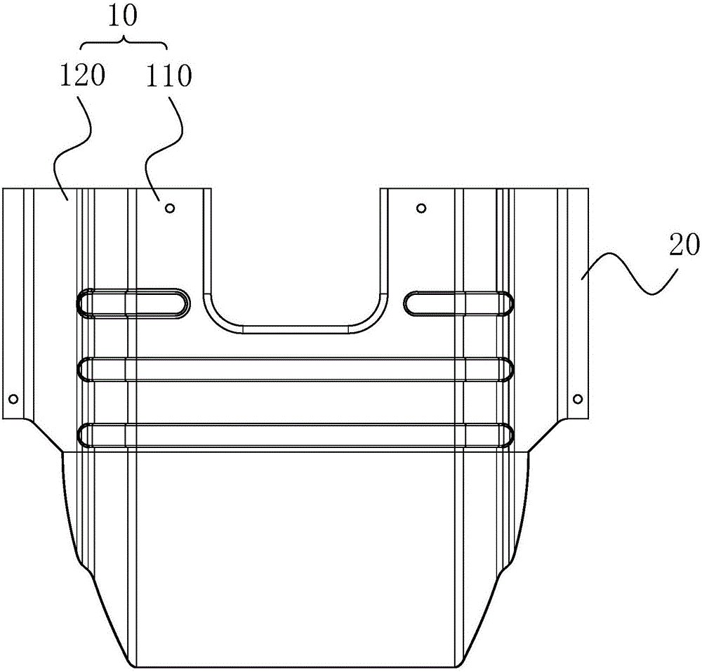
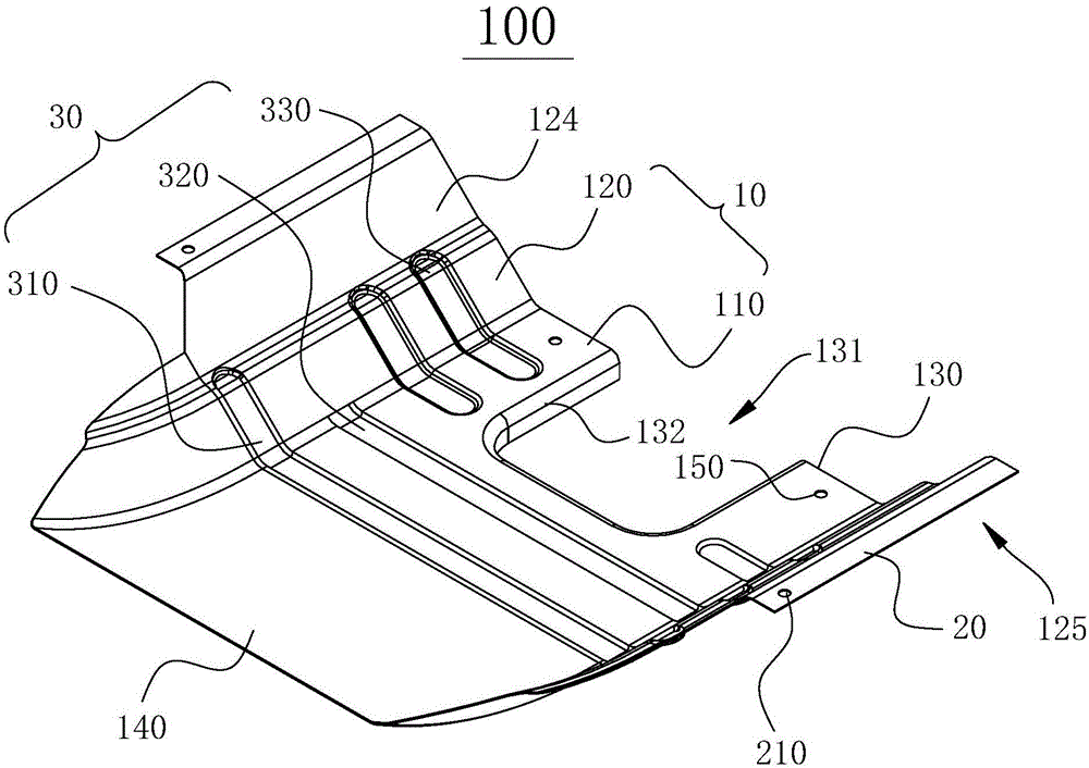
[0033] Please refer to figure 1 , the present embodiment provides a front lower fender 100 of an engine, which includes a fender body 10 and a connecting portion 20 .

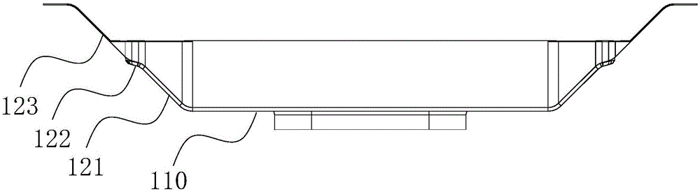
[0034] like figure 2 As shown, the fender body 10 includes a bottom plate 110 and two side plates 120. The side plate 120 is divided into a first side plate 124 and a second side plate 125. The two side plates 120 are symmetrically arranged on both sides of the bottom plate 110. The plate 120 is inclined relative to the bottom plate 110, that is, there is an included angle between the side plate 120 and the bottom plate 110 (such as image 3 shown).

[0035] In this embodiment, the fender body 10 includes a first end 130 and a second end 140 disposed opposite to each other. The first end 130 is provided with a U-shaped notch 131, and the opening of the U-shaped notch 131 faces away from the second end 140, that is, as figure 2 As shown in , the U-shaped opening faces to the right. The edge of the second ...

no. 2 example

[0049] This embodiment provides a truck, including the vehicle frame and the fender 100 at the front lower part of the engine provided by the first embodiment. For other unmentioned parts, refer to the first embodiment or the prior art.

[0050] In this embodiment, the engine is fixed on the vehicle frame, and the front lower fender 100 of the engine is located at the lower front position of the engine, and is connected with the vehicle frame by fasteners. The front lower fender 100 of the engine is arranged outside the engine, so that the engine has a shielding layer, which can block the muddy water and dust splashed by the vehicle during work, so that the engine is well maintained and the service life of the engine is extended, which is equivalent to increasing the service life of the truck , for the user to reduce the economic burden.

[0051] In summary, the present invention provides an engine front lower fender and a truck. The structure of the engine front lower fender ...


PUM


Abstract

The invention relates to a front lower fender of an engine and a truck and belongs to the technical field of truck making. The front lower fender comprises a fender body and a connecting part, wherein the fender body comprises a base plate and two lateral plates, the fender body comprises a first end and a second end which are oppositely arranged, the first end is provided with a U-shaped notch, the edge of the second end is turned towards the engine, the opening of the U-shaped notch faces a direction away from the second end, and one end, away from the base plate, of each lateral plate is connected with the connecting part. The front lower fender with the U-shaped notch is reasonable in structural design, can well attach to the engine and can block muddy water and dust. The truck comprises the front lower fender, the engine is allowed to prevent the dust and the muddy water, and the service life of the truck is prolonged.

Description

technical field [0001] The invention relates to the technical field of truck manufacturing, in particular to a front lower fender of an engine and a truck. Background technique [0002] With the maturity of my country's automobile technology, mobility vehicles have gradually become an important means of transportation for people to travel, and light-duty trucks make people's travel more convenient. [0003] The engine of a light-duty truck is generally located behind the two front wheels. During the running of the vehicle, the muddy water or dust splashed by the two front wheels will splash on the engine from the front lower part of the engine. When the cooling fan and the generator drive belt or pulley, it will cause the belt to slip and accelerate the wear of the belt, which is also not conducive to the cleaning of the engine. In addition, the vortex generated by the airflow at this position will increase the resistance of the car, which is not conducive to the driving ec...

Claims


Application Information

Patent Timeline
Patent Type & Authority Applications(China)
IPC IPC(8): B62D25/16B60R19/54
CPCB60R19/54B62D25/16
Inventor 马李斌龙云朗施明
Owner YUNNAN LIFAN JUNMA AUTOMOBILE
Why Eureka
Try Eureka