Foot retracting device transforming mechanism of biped robot
A biped robot and telescopic device technology, applied in the field of robotics, can solve problems such as slow movement
- Summary
- Abstract
- Description
- Claims
- Application Information
AI Technical Summary
Problems solved by technology
Method used
Image

Examples
Embodiment 1
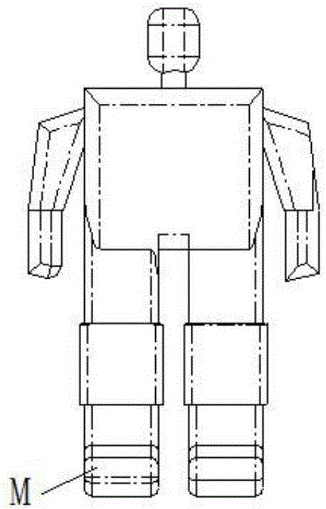
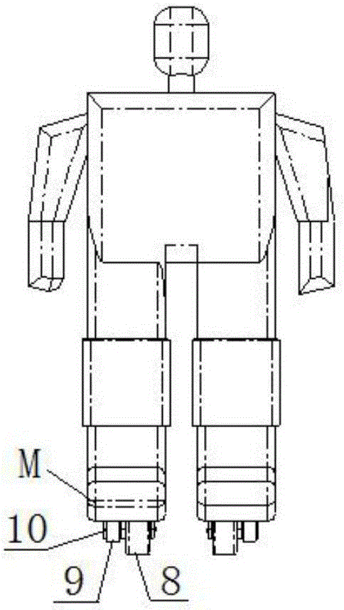
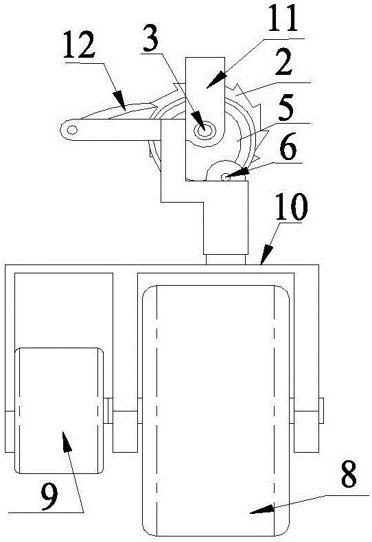
[0059] Such as Figure 3-8 As shown, the deformation mechanism of a biped robot foot telescopic device provided by the present invention includes two groups of telescopic mechanisms installed on the feet of the robot and two groups of walking mechanisms respectively connected with the two groups of telescopic mechanisms; the telescopic mechanism includes Fixed mount 11, telescopic drive motor 1 and telescopic transmission device, fixed mount 11 is fixedly connected with the foot M of robot, telescopic drive motor 1 and telescopic transmission device are installed on the fixed mount 11, and the output shaft of telescopic drive motor 1 and all The above-mentioned telescopic transmission device is connected.
[0060] Described walking mechanism comprises support frame 10, walking drive motor 9 and walking wheel 8, and wherein support frame 10 is connected with described telescopic transmission device, and walking wheel 8 is rotatably installed on the support frame 10 by bearing b...
Embodiment 2
[0071] Such as Figure 9-13 As shown, the telescopic transmission device includes a rotating shaft 3, a cam 5, a worm 13, a worm wheel 14, a roller 6 and a push rod D, wherein the rotating shaft 3 is installed on the fixed frame 11 through the bearing a4, and the cam 5 is sleeved on the rotating shaft 3, And it is connected with the output shaft of the telescopic drive motor 1, the cam 5 is provided with a groove C along the circumferential direction, the push rod D is connected with the support frame 10, the push rod D is provided with a slider aA and a roller 6, the slider aA is connected with the fixed frame The chute B on 11 is slidingly connected, the roller 6 is accommodated in the groove C on the cam 5, and the push rod D on the support frame 10 is in contact with the groove C on the cam 5 through the roller 6. The worm wheel 14 is installed coaxially with the cam 5 , the worm 13 is rotatably mounted on the fixed frame 11 through the bearing c15 and meshed with the worm...
Embodiment 3
[0079] Such as Figure 14-16 As shown, the telescopic transmission device includes a worm 13, a worm wheel 14, a gear 16 and a rack 17, wherein the worm 13 is rotatably mounted on the fixed frame 11 through a bearing c15, and is connected with the output shaft of the telescopic drive motor 1, and the worm wheel 14 And the gear 16 is rotatably installed on the fixed frame 11 through the rotating shaft 3, and the worm wheel 14 is meshed with the worm screw 13. The lower end of the rack 17 is fixedly connected with the support frame 10 , the upper end is slidably connected with the fixed frame 11 , and the gear 16 is engaged with the rack 17 .
[0080] Furthermore, the fixed frame is provided with a guide surface F, and the back surface N of the rack 16 is in contact with the guide surface F on the fixed frame, and can slide relatively.
[0081] The working principle of the present invention is:
[0082] Telescopic drive motor 1 drives worm 13 to drive worm gear 14 to move, wor...
PUM
 Abstract
Description
Claims
Application Information
 - R&D
- Intellectual Property
- Life Sciences
- Materials
- Tech Scout
- Unparalleled Data Quality
- Higher Quality Content
- 60% Fewer Hallucinations
Browse by: Latest US Patents, China's latest patents, Technical Efficacy Thesaurus, Application Domain, Technology Topic, Popular Technical Reports.
© 2025 PatSnap. All rights reserved.Legal|Privacy policy|Modern Slavery Act Transparency Statement|Sitemap|About US| Contact US: help@patsnap.com