Prestressed concrete continuous rigid frame bridge with complete cantilever-construction and construction method thereof

A prestressed, concrete technology, applied in the direction of bridges, bridge construction, erection/assembly of bridges, etc., can solve the problems of long construction period, high cost, high risk, etc., and achieve the effect of simple structure, improved production efficiency and low cost

Inactive Publication Date: 2017-05-31
HUNAN UNIV OF SCI & TECH
View PDF5 Cites 10 Cited by
  • Summary
  • Abstract
  • Description
  • Claims
  • Application Information

AI Technical Summary

Problems solved by technology

The construction of the existing long-span prestressed concrete continuous rigid frame bridge involves the construction of the side-span closure section, the side-span support cast-in-place section and the mid-span closure section. There are multiple key construction nodes and construction process conversions. More cumbersome and long construction period
[0006] For bridges in mountainous areas or across rivers and deep water areas, it is difficult to erect supports or brackets for cast-in-place sections of side spans, requiring preloading and dismantling of supports, and the construction of closing sections of side spans requires process conversion, so This construction method inevitably faces the disadvantages of long construction period, high risk and high cost

Method used


Image

  • Prestressed concrete continuous rigid frame bridge with complete cantilever-construction and construction method thereof
  • Prestressed concrete continuous rigid frame bridge with complete cantilever-construction and construction method thereof
  • Prestressed concrete continuous rigid frame bridge with complete cantilever-construction and construction method thereof

Examples


Embodiment Construction

[0039] The present invention will be further described below in conjunction with the accompanying drawings.

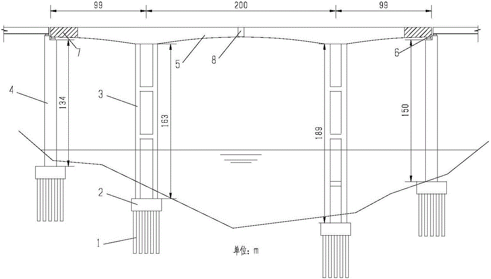
[0040] like Figure 1-3 As shown, take a three-span continuous rigid-frame bridge with a main-span ratio of 0.445 and a main-span ratio of 0.445 as an example. The design and construction process of prestressed concrete continuous rigid frame bridge with full cantilever construction is clarified.

[0041] The full cantilever construction prestressed concrete continuous rigid frame bridge of the present invention comprises a foundation 1, a cap 2, a main pier 3, a side pier 4 and a main girder 5; wherein the top of the side pier 4 is provided with a side pier tension and compression bearing 6, The main beam near the side pier is provided with a side span counterweight section 7, the main span is provided with a main span closing section 8, and the side span has no closing section. The side-main-span ratio is relatively small, 0.445. The mechanical performance of the ...


PUM


Abstract

The invention discloses a prestressed concrete continuous rigid frame bridge with complete cantilever-construction and a construction method thereof. The prestressed concrete continuous rigid frame bridge with the complete cantilever-construction comprises a foundation, a bridge cushion cap, a main pier of bridge, an abutment pier, a main girder, an abutment pier tension-compression bearing, a side span counterweight segment and a main span closure segment; a side span closure segment is not installed in the prestressed concrete continuous rigid frame bridge with the complete cantilever-construction; the ratio of midspan and to side span is less than 0.5, the abutment pier tension-compression bearing is arranged at the top of the abutment pier, the side span counterweight segment is arranged on the side span. The mechanical properties of the prestressed concrete continuous rigid frame bridge with the complete cantilever-construction are mainly achieved by reasonable configuration of prestress and temporary counterweight during the construction of the complete cantilever. The prestressed concrete continuous rigid frame bridge with the complete cantilever-construction and the construction method do not have the process of the side span closure segment, the construction steps are simplified, the construction workload is reduced, the construction period is shortened and the construction risk of a high pier support is reduced.

Description

technical field [0001] The invention belongs to the technical field of bridges, and in particular relates to a prestressed concrete continuous rigid frame bridge with full cantilever construction and a construction method thereof. Background technique [0002] Continuous rigid frame bridges are widely used in the design of highway bridges in my country because of their advantages such as clear structural stress, large spanning capacity, comfortable driving, low cost, and applicable to various construction methods. [0003] In the 1950s, the cantilever construction method appeared as a brand-new construction method and was widely used in long-span girder bridges. Therefore, the span of the prestressed concrete box girder bridge is further enlarged, and its application can be vigorously developed. At present, the maximum main span of the continuous rigid frame bridge has exceeded 300m, and it is widely used in mountains, canyons and river-crossing areas. [0004] Existing lo...

Claims


Application Information

Patent Timeline
Patent Type & Authority Applications(China)
IPC IPC(8): E01D21/10
CPCE01D21/10
Inventor 汪建群吕鹏许巧陈添乐
Owner HUNAN UNIV OF SCI & TECH
Why Eureka
Try Eureka