Drill floor sliding rail

A drilling floor and sliding technology, applied in drilling equipment, earthwork drilling, water conservancy projects, etc., can solve problems such as hidden safety hazards, inconvenience in manufacturing, debugging and testing of sliding drilling floors, and achieve stable performance, reliable and convenient. The effect of locking in place and high safety performance

Inactive Publication Date: 2017-05-31
LANZHOU LS GRP +1
View PDF6 Cites 2 Cited by
  • Summary
  • Abstract
  • Description
  • Claims
  • Application Information

AI Technical Summary

Problems solved by technology

There are many ways to slide the drill floor, but at present, the slide of the drill floor is mostly carried out on the cantilever beam of the derrick. Due to the

Method used


Image

  • Drill floor sliding rail
  • Drill floor sliding rail
  • Drill floor sliding rail

Examples


Embodiment Construction

[0025] The present invention will be further described in detail below in conjunction with the drawings.

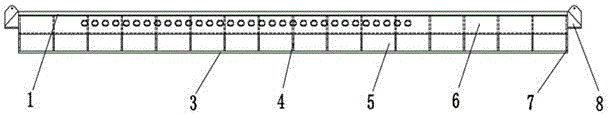
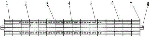
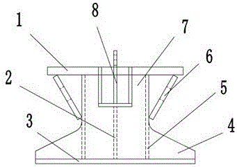
[0026] Such as Figure 1 to Figure 3 The slide track of a drill floor shown includes an upper top plate 1 and a lower bottom plate 3 parallel to each other, a web 2 perpendicularly connected to the upper top plate 1 and the lower bottom plate 3, and the web 2 is connected to the upper top plate 1 and the lower bottom plate In the longitudinal middle part of 3, several "L"-shaped transverse ribs 4 are evenly arranged on both sides of the web 2. A longitudinal rib 5 is installed between two adjacent transverse ribs 4, and the longitudinal ribs 5 are Linearly symmetrically distributed on both sides of the web 2, the longitudinal ribs 5 are mounted on the side away from the web 2 with diagonal bracing plates 6. The top of the diagonal bracing plate 6 is connected with the bottom surface of the upper top plate 1, and the bottom of the diagonal bracing plate 6 is connected with T...


PUM


Abstract

The invention discloses a drill floor sliding rail. The drill floor sliding rail comprises an upper top plate, a lower bottom plate and a web, wherein the upper top plate and the lower bottom plate are parallel to each other, and the web is perpendicularly connected with the upper top plate and the lower bottom plate; a plurality of transverse rib plates are uniformly arranged on the two sides of the web; longitudinal rib plates are mounted between every two adjacent transverse rib plates; the multiple longitudinal rib plates are linearly and symmetrically distributed on the two sides of the web; inclined bracing plates are mounted on the side faces, far from the web, of the longitudinal rib plates; the top of each inclined bracing plate is connected with the bottom face of the upper top plate; and the bottom of each inclined bracing plate is connected with the middle part of the corresponding transverse rib plate. A rail main body comprises the upper top plate, the web, the lower bottom plate, the transverse rib plates and the longitudinal rib plates. Four rails are mounted at the bottoms of drill floor supports of a slidable type drill floor in a matched mode so that adjusting and testing of the slidable type drill floor can be achieved without complex work on a cantilever beam, and thus great convenience is bought for the development work of the drill floor; and the rail main body is formed by assembling, the stable property is good, manufacturing and assembling are convenient and fast, and the manufacturing cost is low.

Description

Technical field [0001] The invention relates to the technical field of marine drilling equipment, in particular to a slip track of a drill floor. Background technique [0002] The rig design of jack-up offshore drilling platform is mostly slippery. There are many ways to slide the drill floor, but at present, most of the slide of the drill floor is carried out on the cantilever beam of the derrick. Due to the high height of the cantilever beam from the ground, the manufacture, debugging and testing of the slideable drill floor cause inconvenience. , There are certain security risks. Summary of the invention [0003] The purpose of the present invention is to provide a drill floor sliding track, which can complete the manufacture, debugging and testing of the sliding drill floor at a low position without complicated work on the cantilever beam, which is convenient for the research and development design of the sliding drill floor . [0004] In order to achieve the above objectives...

Claims


Application Information

Patent Timeline
IPC IPC(8): E02B17/00E21B15/00E21B15/02
CPCE02B17/00E21B15/003E21B15/02
Inventor 张彦秋陆辉张建赵世刚成斌豆乔
Owner LANZHOU LS GRP
Why Eureka
Try Eureka