Electric Power Tool

Active Publication Date: 2018-06-14
ROBERT BOSCH GMBH
View PDF13 Cites 1 Cited by
  • Summary
  • Abstract
  • Description
  • Claims
  • Application Information

AI Technical Summary

Benefits of technology

The invention provides an electric power tool with a reliable and durable brake system that allows for extended service life of the entire tool. This is achieved by designing the brake system in a way that reduces mechanical stress on the brake elements and ensures stability and minimal wear. Overall, this allows for a significant improvement in the performance and durability of the electric power tool.

Problems solved by technology

A disadvantage of this prior art is that the two first brake elements of the magnetic-field brake unit are relatively heavily mechanically loaded by their rotatable arrangement, whereby their service life can be reduced and therefore the product service life of the electric power tool as a whole can be reduced.

Method used


Image

  • Electric Power Tool
  • Electric Power Tool
  • Electric Power Tool

Examples


Embodiment Construction

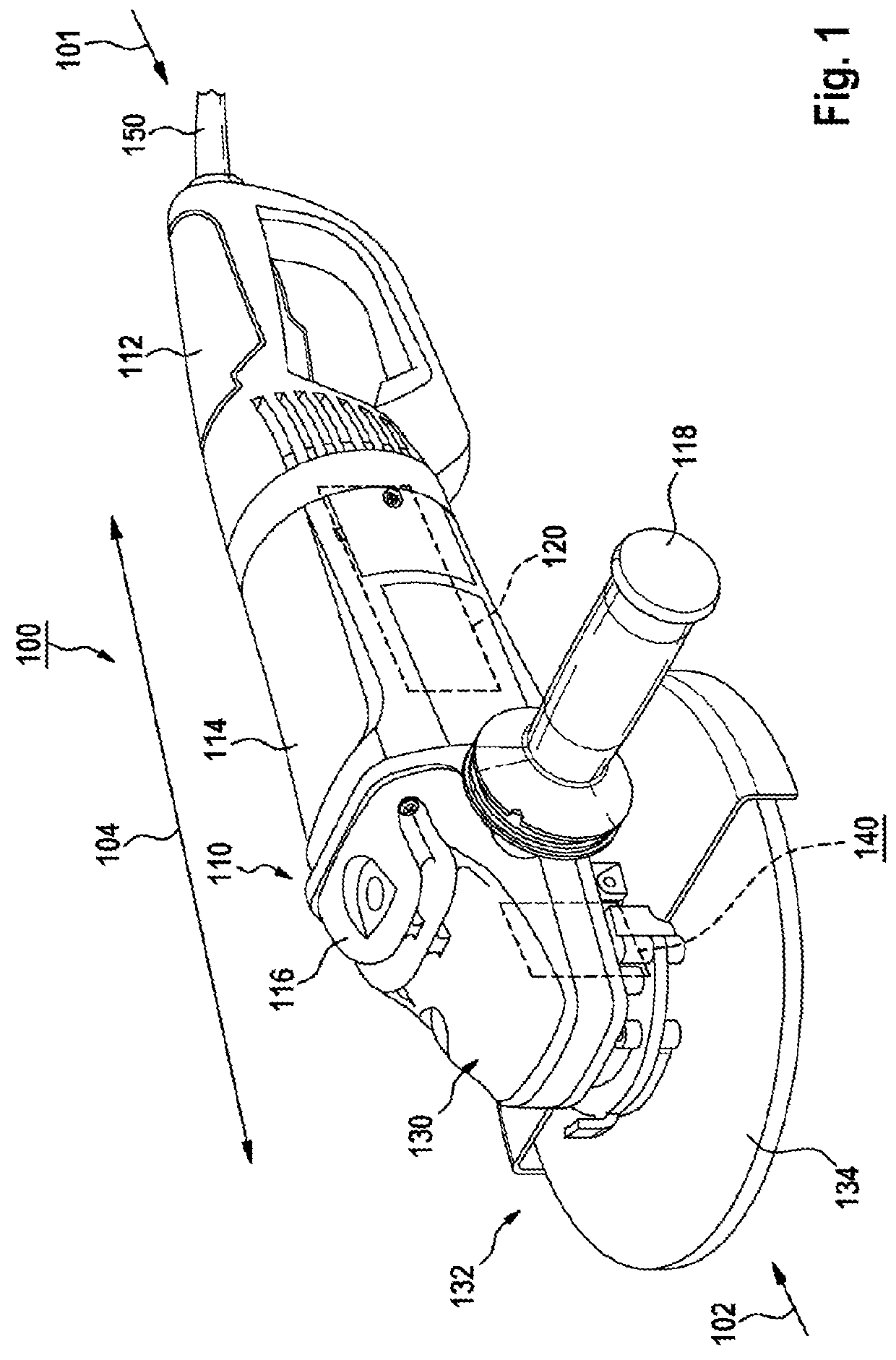
[0041]FIG. 1 shows an electric power tool 100 formed as an angle grinder with a brake apparatus 140 in accordance with one embodiment. It should be noted that the electric power tool 100 is described merely by way of example as an angle grinder and not so as to limit the present invention. Rather, the invention can be applied in the case of electric power tools, in particular portable electric power tools, which are fitted or can be fitted with a drive motor and the brake apparatus according to the invention. The term “portable electric power tool” is understood within the context of the invention to mean an electric power tool which can be transported by a user without use of a transport machine. In addition, the brake apparatus can be integrated in a modular manner in any electric power tool, for example via a plug connection. Furthermore, the electric power tool 100 preferably has a mass less than 50 kg, preferably less than 20 kg, and particularly preferably less than 10 kg.

[004...


PUM


Abstract

An electric power tool includes an output shaft, drivable by an associated drive motor, and a brake apparatus for braking the output shaft rotating in the unpowered state of the associated drive motor. The output shaft is mounted in a rotatable manner in an associated housing and the brake apparatus has a magnetic-field brake unit with at least one first and one second brake element. The first brake element is arranged radially with respect to the output shaft in a rotationally fixed manner in the associated housing and includes at least one first and one second magnetic pole configured to generate a magnetic field that alternates in the circumferential direction of the output shaft. The second brake element is magnetically conductive and rotationally connected to the output shaft via an activatable coupling device.

Description

PRIOR ART[0001]The present invention relates to an electric power tool with an output shaft drivable by an associated drive motor and with a brake apparatus for braking the output shaft rotating in the unpowered state of the associated drive motor, wherein the output shaft is rotatably mounted in an associated housing and the brake apparatus comprises a magnetic-field brake unit having at least one first and one second brake element.[0002]An electric power tool of this type having a drivetrain and a magnetic-field brake unit is known from DE 10 2010 043 185 A1. This magnetic-field brake unit has two first brake elements, which are arranged rotatably in a housing associated with the electric power tool and which are formed in the manner of magnet rings, and also a second brake element, which is arranged non-rotatably between the two first brake elements and which is formed in the manner of a copper disc.[0003]A disadvantage of this prior art is that the two first brake elements of th...

Claims


Application Information

Patent Timeline
IPC IPC(8): B23Q11/00B24B47/26H02K7/104B25F5/00B24B23/02H02K7/14
CPCB23Q11/0092B24B47/26H02K7/104B25F5/001B24B23/028B24B23/022H02K7/145
Inventor LABER, SEBASTIANBAYER, HEIKOESENWEIN, FLORIANLUTZ, MANFRED
Owner ROBERT BOSCH GMBH
Why Eureka
Try Eureka