Antifreeze screw pump screw to increase the flow rate of liquid in the pump

A technology for adding pumps and screw pumps, applied in the direction of liquid fuel engines, pumps, pump components, etc., can solve the problems of difficult suction and discharge, maintaining the temperature of the suction and discharge liquid of the screw pump, and damage to the pump body of the screw pump, and achieve the effect of avoiding the solidification of the liquid.

Active Publication Date: 2019-03-05
四川凯创机电设备有限公司
View PDF10 Cites 0 Cited by
  • Summary
  • Abstract
  • Description
  • Claims
  • Application Information

AI Technical Summary

Problems solved by technology

[0004] The technical problem to be solved by the present invention is that the screw pump is most suitable for sucking and discharging viscous liquid, and the viscous liquid is easy to solidify when the temperature is low, and it is difficult to suck and discharge, and the forced suction and discharge will easily cause damage to the pump body of the screw pump. Antifreeze screw pump screw with liquid flow rate solves the problem of maintaining the temperature of the suction and discharge liquid of the screw pump

Method used


Image

  • Antifreeze screw pump screw to increase the flow rate of liquid in the pump

Examples


Embodiment 1

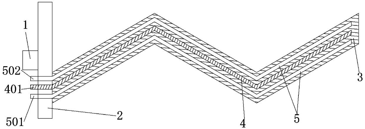
[0020] like figure 1 As shown, the antifreeze screw pump screw of the present invention that increases the liquid flow rate in the pump includes a cardan shaft 1, a cardan shaft seat 2 and a screw rod 3 connected in sequence, extending from the joint of the cardan shaft seat 2 and the screw rod 3 to the screw rod 3 The diameter of the hole is 1 / 6 of the screw diameter, and the heating wire 4 is arranged in the hole, and the heating wire 4 passes through the universal shaft seat 2 and connects with the electric heating interface 401 on the universal shaft seat 2 . By setting the electric heating wire in the screw, when the ambient temperature is too low, turn on the power supply of the electric heating interface, and the electric heating wire works to heat the screw, thereby heating the liquid in the screw pump and ensuring the temperature of the liquid. An insulating and heat-conducting rubber is arranged between the heating wire 4 and the screw 3 . Because the heating wire i...

Embodiment 2

[0022] The difference between this embodiment and Embodiment 1 is that the two hollow tube holes 5 are connected to each other, and the two hollow tube holes 5 pass through the cardan shaft seat 2 and connect with the water inlet 501 and the water outlet 502 respectively. connect. The auxiliary heating or cooling of the pump body is realized by injecting water into the hollow tube hole. The two hollow tube holes 5 pass through the universal shaft seat 2 and are respectively connected to the water inlet 501 and the water outlet 502 , wherein one hollow tube hole 5 is connected to the water inlet 501 and the other hollow tube hole 5 is connected to the water outlet 502 . Ensure that the flow rate at the water inlet and outlet is relatively stable, and the system stability is high.


PUM


Abstract

The invention discloses an anti-freezing crew-pump capable of increasing the flow velocity of a liquid in a pump. The anti-freezing crew-pump comprises a universal shaft, a universal shaft seat and a screw rod which are sequentially connected, wherein a hole is punched in the extension direction from the connected part of the universal shaft seat and the screw rod to the screw rod, and an electric heating wire is arranged in the hole; the electric heating wire passes through the universal shaft seat and is connected with an electric heating interface in the universal shaft seat. Through the method of arranging the electric heating wire in the screw rod, power supply of the electric heating interface is connected when the environment temperature is too low, and the electric heating wire works and heats the screw rod, so that the liquid in a screw pump is heated and the temperature of the liquid is ensured. The anti-freezing crew-pump has the advantages that the temperature of the liquid in a pump body can be kept, solidification of the liquid is avoided, and the anti-freezing crew-pump is provided with a water cooling pipe, thereby facilitating cooling or heating.

Description

technical field [0001] The invention relates to a screw pump accessory, in particular to an antifreeze screw pump screw for increasing the liquid flow rate in the pump. Background technique [0002] The screw pump is a rotary pump that relies on the volume change and movement of the meshing space formed by the pump body and the screw to deliver or pressurize the liquid. Screw pumps are divided into single screw pumps, twin screw pumps and triple screw pumps according to the number of screws. When the active screw rotates, it drives the driven screw engaged with it to rotate together, the volume of the screw engagement space at one end of the suction chamber increases gradually, and the pressure decreases. The liquid enters the meshing space volume under the action of the pressure difference. When the volume increases to the maximum and a sealed cavity is formed, the liquid moves axially in each sealed cavity until it is discharged from one end of the cavity. At this time,...

Claims


Application Information

Patent Timeline
Patent Type & Authority Patents(China)
IPC IPC(8): F04C15/00F04C2/08
CPCF04C2/084F04C15/0096F04C2240/603
Inventor 杨东
Owner 四川凯创机电设备有限公司
Why Eureka
Try Eureka