air flow cut-off device

A cut-off device and airflow technology, which is applied in the direction of fluid pressure actuators, servo motor components, mechanical equipment, etc., can solve the problems of inability to reflect the working performance, easy failure of the valve core, and difficult repair, etc., to improve manufacturability and economic durability High performance, convenient for daily maintenance, convenient for production and installation

Active Publication Date: 2018-02-09
重庆完镁镁制品有限公司
View PDF4 Cites 0 Cited by
  • Summary
  • Abstract
  • Description
  • Claims
  • Application Information

AI Technical Summary

Problems solved by technology

[0002] In industrial control, compressed gas is usually used to push the actuator to achieve a certain function. Usually, a cut-off element is required for the connection between the actuators to control the on-off. Although the existing valve control effect is good, it is easy to damage And it is not easy to repair. The core component of the valve core is complex in structure, and it is easy to be damaged and difficult to repair. After the airflow enters the valve body, it will directly cause severe impact on the valve core. Over time, the valve core is prone to failure; on the other hand, in industrial control and Not all equipment components that control the flow of air flow require high airtight precision. The use of some existing gas valves not only cannot reflect their working performance, but also causes waste. Because the matching gap between parts is too small, it is also more likely to be damaged. For Extensive gas control with impurities is neither practical nor economical

Method used


Image

  • air flow cut-off device
  • air flow cut-off device
  • air flow cut-off device

Examples


Embodiment Construction

[0017] The implementation of the present invention will be illustrated by specific specific examples below, and those skilled in the art can easily understand other advantages and effects of the present invention from the contents disclosed in this specification.

[0018] Below in conjunction with accompanying drawing and embodiment the present invention will be further described:

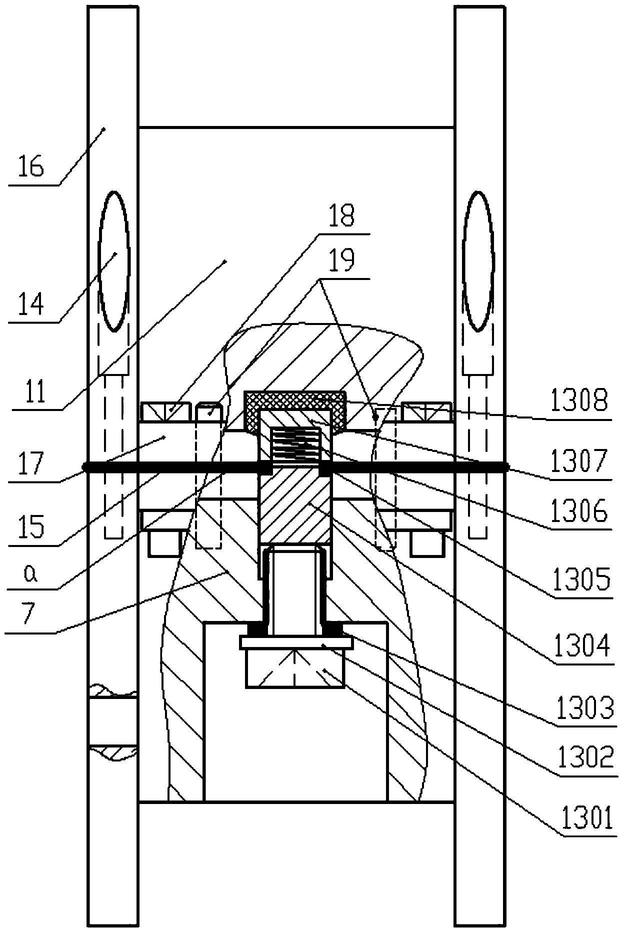
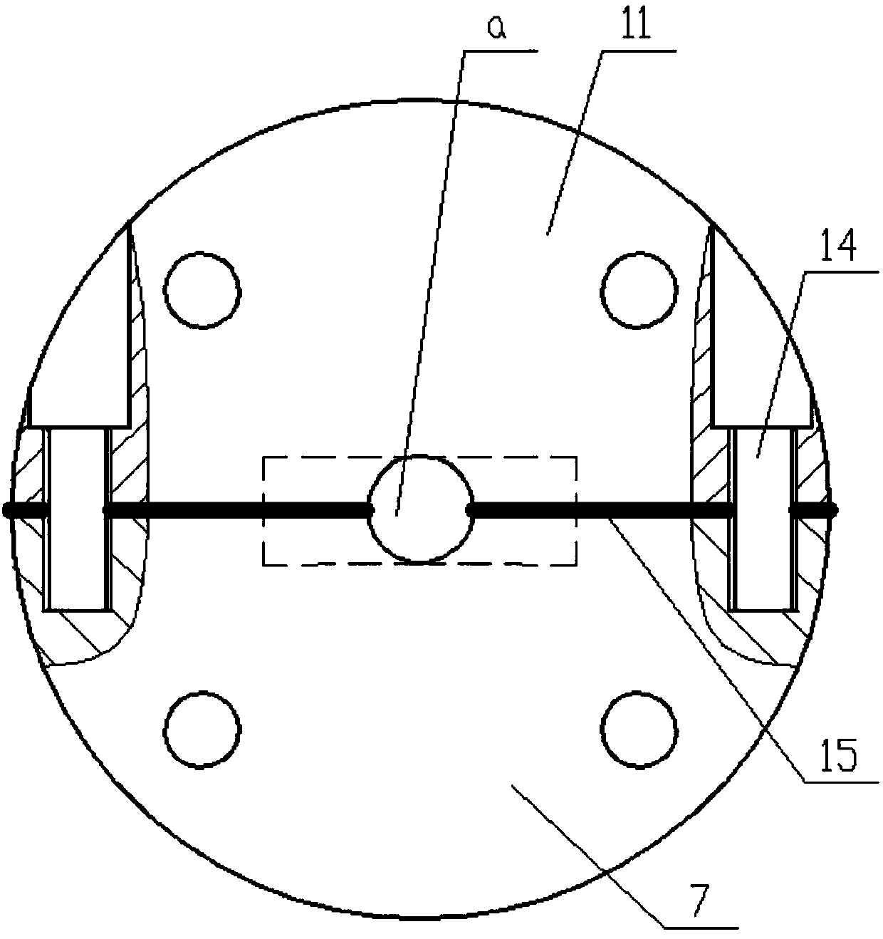
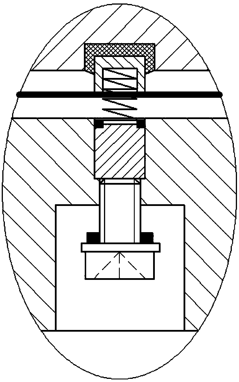
[0019] Such as figure 1 As shown in -2, an air flow cut-off device includes a shell, and the shell includes an upper shell 11 and a lower shell 7 with axial through grooves inside, and the upper shell 11 and the lower shell 7 are connected after being combined. The groove forms an air channel a arranged in the axial direction and open at both ends. The air channel a may be in the shape of any cavity channel, and the two ends of the air channel a are preferably made into round holes. After splicing, a complete flange plate 16 is also formed at both ends of the shell respectively, and each flange pl...


PUM


Abstract

The invention discloses an airflow stop device. The airflow stop device comprises a shell consisting of an upper shell and a lower shell; the upper shell and the lower shell are spliced to form an air runner opened at two ends; flange plates are respectively formed at two ends of the shell; each flange plate is provided with fastening bolt counter bores for connecting the upper shell with the lower shell; two bolt counter bores in each flange plate are symmetrical about a vertical center surface of the axle of the flange plate; and a sealing flat pad is arranged between the spliced end surfaces of the upper shell and the lower shell. The airflow stop device further comprises an adjusting bolt wound with a sealing filler and upwards screwed from the bottom of the lower shell; the adjusting bolt is ejected to a flashboard in the lower shell; the top end of the flashboard is sleeved with a sealing ring; a spring base is arranged above the sealing ring; and two ends of a spring are respectively fixed on the spring base and the flashboard. The device is simple and compact in structure, liable to manufacture and maintain and excellent in economy and durability.

Description

technical field [0001] The invention belongs to the technical field of air flow control, and in particular relates to an element for controlling air flow interruption. Background technique [0002] In industrial control, compressed gas is usually used to push the actuator to achieve a certain function. Usually, a cut-off element is required for the connection between the actuators to control the on-off. Although the existing valve control effect is good, it is easy to damage And it is not easy to repair. The core component of the valve core is complex in structure, and it is easy to be damaged and difficult to repair. After the airflow enters the valve body, it will directly cause severe impact on the valve core. Over time, the valve core is prone to failure; on the other hand, in industrial control and Not all equipment components that control the flow of air flow require high airtight precision. The use of some existing gas valves not only cannot reflect their working perf...

Claims


Application Information

Patent Timeline
Patent Type & Authority Patents(China)
IPC IPC(8): F15B13/02
CPCF15B13/02
Inventor 李朝安
Owner 重庆完镁镁制品有限公司
Why Eureka
Try Eureka