Minimum flow valve

A technology of minimum flow and valve seat, applied in the direction of valve lift, valve device, engine components, etc., can solve the problems of aggravated valve core, cavitation, valve leakage, etc., to avoid valve leakage, increase contact rigidity, and increase deformation Effect

Pending Publication Date: 2017-05-31
徐传堂
View PDF10 Cites 0 Cited by
  • Summary
  • Abstract
  • Description
  • Claims
  • Application Information

AI Technical Summary

Problems solved by technology

After the labyrinth pin is damaged, the feed water entering the upper part of the pre-opening valve cannot be decompressed and directly flushes the sealing surface of the pre-opening valve, resulting in damage to the pre-opening valve valve line and further valve leakage
2. Caused by blowing of the valve valve line; during the opening process of the valve, the high-pressure water supply directly flushes the valve line of the main valve core and causes the valve to leak; usually there are circular defects uniformly distributed in the circumferential direction on the blown valve core. On the one hand, The high-pressure feed water directly washes the valve line, causing the sealing surface of the valve core to be partially blown, the valve cannot be tightly closed, and at the same time causes damage to the sealing surface of the valve seat; on the other hand, since the minimum flow valve is followed by a deaerator, In this way, the pressure difference between the front of the valve and the back of the valve is very large. When the valve is closed, due to the partial leakage of the valve line, the phenomenon of "cavitation" will further occur, which will further aggravate the damage of the valve core and valve seat.
In summer, when the unit is running at high load, the output of the steam pump cannot keep up due to the leakage of the recirculation control valve. Generally, the maximum continuous output of a 600MW supercritical unit is 634.18MW, and it is difficult to bring the unit load to 620MW in summer.

Method used


Image

  • Minimum flow valve
  • Minimum flow valve

Examples


Embodiment Construction

[0016] The preferred embodiments of the present invention will be described in detail below in conjunction with the accompanying drawings, so that the advantages and features of the present invention can be more easily understood by those skilled in the art, so as to define the protection scope of the present invention more clearly.

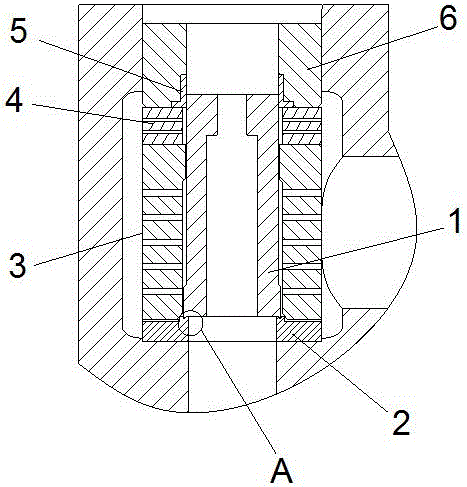
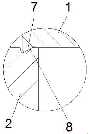
[0017] see figure 1 with figure 2 , the embodiment of the present invention includes:

[0018] A minimum flow valve, comprising: a valve core 1, a valve seat 2, a valve cage 3, a cage 4, a guide sleeve 5 and a valve cap gasket 6; the valve core 1 is located on the valve seat 2, and the valve cage 3 is covered On the spool 1; the cage 4 is located on the cage 3, and the side walls of the cage 3 and the cage 4 are provided with a plurality of throttle holes, and the throttle holes on the cage are smaller than the throttle of the cage hole; the guide sleeve 5 is arranged on the cage 4, the bonnet gasket 6 is arranged on the cage and the bonnet ga...


PUM


Abstract

The invention discloses a minimum flow valve comprising a valve core, a valve seat, a seat cage, a cage cover, a guiding sleeve and a valve cap spacer. The valve core is located on the upper portion of the valve seat. The valve cage covers the valve core. The cage cover is located on the valve cage. A plurality of throttling holes are formed in the side walls of the valve cage and the cage cover. The throttling holes in the cage cover are smaller than the throttling holes in the valve cage. The guiding sleeve is arranged on the cage cover. The valve cap spacer is arranged on the cage cover and presses the guiding sleeve. An inward-inclining valve core sealing face is arranged on the lower end face of the valve core and close to the inner wall of the valve core. A valve seat sealing face corresponding to the valve core sealing face is arranged on the valve seat. A 316 L stainless steel layer is welded on the valve core, and a Stellite alloy layer is welded on the 316 L stainless steel layer. A Stellite alloy layer is welded on the valve seat. By means of the mode, the blowing loss of a high-temperature and high-pressure valve line can be avoided, and the problem of the internal leakage of the minimum flow valve and relevant valves is solved.

Description

technical field [0001] The invention relates to the field of high temperature and high pressure regulating valves, in particular to a minimum flow valve. Background technique [0002] CCI's labyrinth minimum flow valve is the first product of CCI manufacturers and is also a leading product. It works well in the operation of subcritical 300MW and 600MW units. However, with the operation of supercritical and ultra-supercritical units and the continuous improvement of related parameters , Especially with the increase of water supply pressure, more and more valves are leaking. According to statistics, in the supercritical 600MW unit and ultra-supercritical 660MW / 1000MW unit, the minimum flow valve of the power plant is produced by CCI company. Leakage of varying degrees often occurs over time. [0003] Through the observation of the damaged parts and the comprehensive analysis of the situation learned on site, there are two important reasons for the leakage of the minimum flow ...

Claims


Application Information

Patent Timeline
Patent Type & Authority Applications(China)
IPC IPC(8): F16K1/36F16K1/42F16K1/46
CPCF16K1/36F16K1/42F16K1/465
Inventor 徐传堂
Owner 徐传堂
Why Eureka
Try Eureka