

Method for mounting wind pipe by self-locking wind pipe lifting frame
A technology for air ducts and hangers, which is applied in the field of air duct installation using self-locking air duct hangers, which can solve problems such as low efficiency, adjustment errors, and cumbersome procedures, so as to improve construction efficiency, ensure stability, even force effect
- Summary
- Abstract
- Description
- Claims
- Application Information
AI Technical Summary
Problems solved by technology
Method used
Image

Examples
Embodiment 1
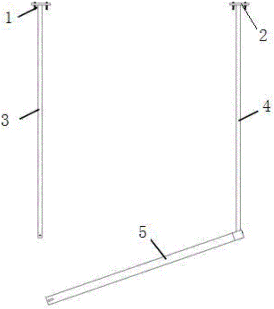
[0032] Example 1, see Figure 1-Figure 7 , a method for installing an air duct using a self-locking air duct hanger, comprising the following steps:
[0033] Step 1. Establish a three-dimensional model of the building according to the wind, water, and electricity systems and the floor plan of the building, and set information such as the material and size of the air duct in the three-dimensional model;
[0034] Step 2. Through the in-depth design of the three-dimensional model, the mechanical and electrical professional technicians reasonably arrange the position of each air duct in the air duct pipeline, and determine the elevation and direction of the air duct;
[0035] Step 3. Based on the deepened air duct model, design its supports and hangers, and perform force calculations. According to the force calculation results, reasonably arrange the use form and spacing of the air duct hangers, and according to the wind duct after the layout is completed, Generate a cross-sectio...
Embodiment 2
[0042] Example 2, see Figure 8 , Figure 9 , the difference from Example 1 is: the first boom 3 and the second boom 4 are all telescopic booms; An external thread 12 is provided, and a waist hole 14 is also provided on the telescopic sleeve rod 10; a protrusion 15 is provided on the upper end of the telescopic main rod 11, and when the telescopic main rod 11 is inserted into the telescopic sleeve rod 10, the protrusion 15 is placed In the waist hole 14, and protrude the telescopic sleeve rod 10; Before installation, first adjust the height of the first boom and the second boom, the T-shaped self-locking member 9 passes through the connecting hole and the threaded connection hole, so that the cross arm overlaps with the second boom, and then installs; The jacking device 17 lifts the air duct 18 to the preset position; pulls out the T-shaped self-locking member 9, makes the cross arm 5 rotate 270° around the second suspender 4, and inserts the lower end of the first suspender...
Embodiment 3
[0043] Embodiment 3 is different from Embodiment 2 in that one of the suspenders is a height-adjustable telescopic suspender, and the other suspender is a fixed-height suspender.
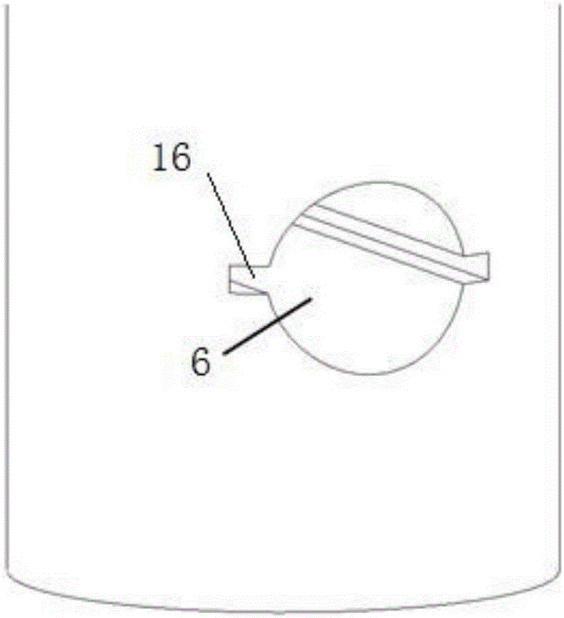
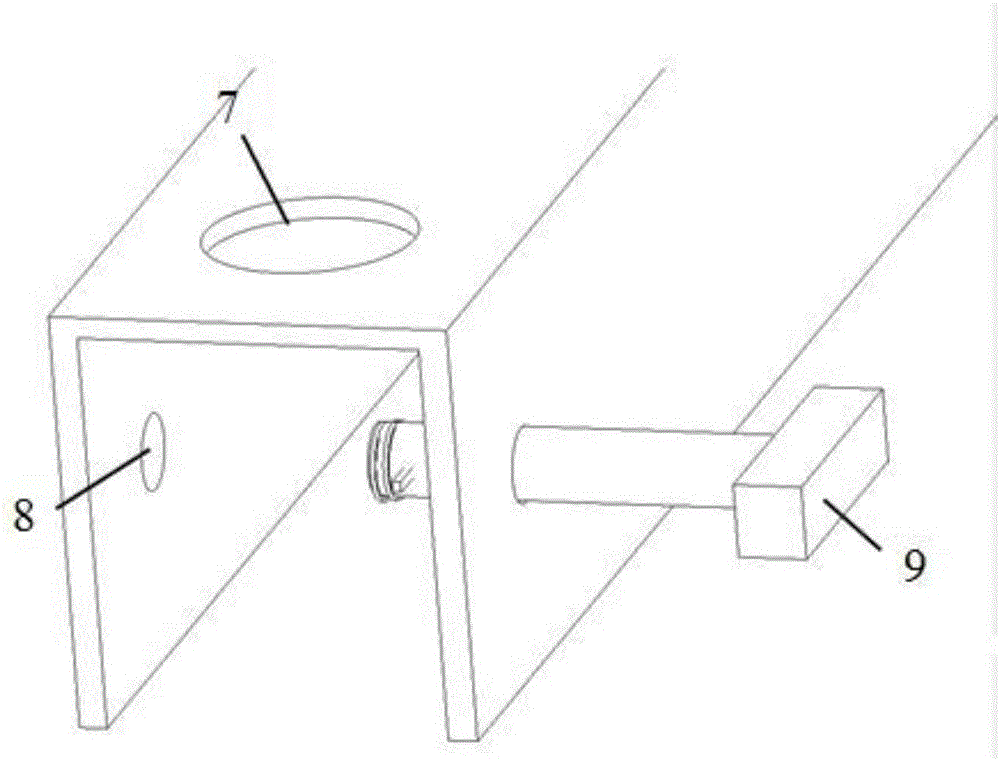
[0044] In the present invention, the height and size of the air duct hanger must be determined before installation, and once determined, cannot be changed during installation and use. The self-locking function of the air duct hanger is realized through the T-shaped self-locking member 9 , the first through hole 6 , the insertion hole 7 and the threaded connection hole 8 .
[0045] Example 1 uses a fixed-height self-locking air duct hanger for air duct installation, Example 2 uses an adjustable-height self-locking air duct hanger for air duct installation, and Example 3 uses one of the suspenders as an adjustable Adjust the height of the telescopic suspender, and the other suspender is a self-locking air duct hanger composed of a fixed height suspender for air duct installation. During actual construc...
PUM
 Abstract
Description
Claims
Application Information