Hydrogen storage device utilizing metallic compound

A technology of metal compound and metal compound layer, which is applied in fixed-capacity gas storage tanks, gas/liquid distribution and storage, geometry/arrangement/size of container structure, etc., can solve problems such as energy consumption, increase storage capacity, solve The effect of security concerns

Inactive Publication Date: 2017-05-31
大连爱特流体控制有限公司
View PDF7 Cites 0 Cited by
  • Summary
  • Abstract
  • Description
  • Claims
  • Application Information

AI Technical Summary

Problems solved by technology

[0003] Conclusion Storing hydrogen with compressed gas is very energy-intensive

Method used


Image

  • Hydrogen storage device utilizing metallic compound

Examples


Embodiment Construction

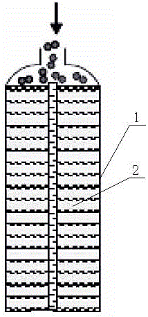
[0010] Metal compound hydrogen storage device of the present invention such as figure 1 As shown, the hydrogen storage tank 1 is provided with a metal compound layer 2, and the metal compound layer 2 is a metal hydride fine powder. Metal hydride (LaNi4.25Al0.75) fine powder repeats hydrogen absorption and desorption actions, after 1 cycle (left picture) and 10 cycles. Metal hydride expands hydrogen during absorption and forms alloy hydrogen after release, and its expansion and contraction process cannot be excessively restricted. If a large amount of metal hydride powder is present due to expansion restrictions or lack of space, the pressure will be on the container walls and may eventually deform or damage the container. How to increase the stored hydrogen density is the most critical issue. Hydrogen storage using alloy hydrogen is a thermally driven process. The heat needs to be disposed of during the hydrogen charging and discharging process. Heat transfer during hydrog...


PUM


Abstract

The invention provides a hydrogen storage device utilizing a metallic compound. A metal compound layer is arranged in a hydrogen storage pot and made of metal hydride fine powder. According to the hydrogen storage device utilizing the metallic compound, by using the metallic compound for hydrogen storage, low-pressure storage can be conducted, the low-pressure storage quantity is increased, and the doubt about safety of traditional high-pressure storage is avoided.

Description

technical field [0001] The invention relates to the technical field of hydrogen storage, in particular to a hydrogen storage device. Background technique [0002] The existing hydrogen storage methods usually use compressed hydrogen to 5,000 pounds (340 atmospheres) and 10,000 (680 atmospheres), which require energy consumption of 36 MJ / kg and 47 MJ / kg, corresponding to the low calorific value of 30-40% hydrogen (LHV), very energy consuming. [0003] Conclusion Storing hydrogen with compressed gas is very energy intensive. Contents of the invention [0004] In order to solve the above-mentioned problems existing in the existing hydrogen storage methods, the present invention provides a metal compound hydrogen storage device. [0005] The technical solution adopted by the present invention to achieve the above purpose is: a metal compound hydrogen storage device, the hydrogen storage tank 1 is provided with a metal compound layer 2 . [0006] The metal compound layer 2 i...

Claims


Application Information

Patent Timeline
Patent Type & Authority Applications(China)
IPC IPC(8): F17C1/06F17C11/00
CPCF17C1/06F17C11/005F17C2201/0104F17C2203/0636F17C2221/012Y02E60/32
Inventor 吴高峰丁杰李旭涛
Owner 大连爱特流体控制有限公司
Why Eureka
Try Eureka