
Temperature controller for refrigerator

A technology for thermostats and refrigerators, applied in applications, household appliances, household refrigeration devices, etc., can solve the problems of inability to reduce, inability to quickly and slowly cool refrigerators, and inability to control the working efficiency of compressors, so as to save power and structure Simple, efficient results

Active Publication Date: 2017-05-31
滁州聚米电气技术有限公司
View PDF5 Cites 0 Cited by
  • Summary
  • Abstract
  • Description
  • Claims
  • Application Information

AI Technical Summary

Problems solved by technology

With the development of cities, the demand for refrigerators is also gradually increasing. Refrigerators are gradually being used by hotels, hotels, hospitals and some discerning city businessmen to keep medicine and food fresh. Now refrigerators have become indispensable in people's lives. For daily necessities, thermostats are installed on existing refrigerators. Patent U203536298U proposes a thermostat for refrigerators, which can adjust the temperature of the refrigerator and has high stability. However, due to the setting of the return spring, when the temperature sensor When the action force of the tube on the spiral temperature sensing plate is less than the tension of the return spring, the return spring can drive the eccentric to rotate, and the temperature cannot be lowered to the specified temperature, and it cannot control the working efficiency of the compressor, and cannot make the refrigerator cool quickly or slowly. Refrigeration, for this reason we propose a thermostat for refrigerators to solve the above problems

Method used


Image

  • Temperature controller for refrigerator
  • Temperature controller for refrigerator
  • Temperature controller for refrigerator

Examples


Embodiment Construction

[0016] The following will clearly and completely describe the technical solutions in the embodiments of the present invention with reference to the accompanying drawings in the embodiments of the present invention. Obviously, the described embodiments are only some, not all, embodiments of the present invention.

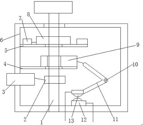
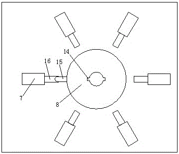
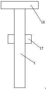
[0017] refer to Figure 1-4 , a thermostat for a refrigerator, comprising a casing 6 and a temperature sensing tube 3 installed on the casing 6, a first rotating shaft 1 is arranged inside the casing 6, and the side walls on both sides of the first rotating shaft 1 are provided with Block 17, the top of the first rotating shaft 1 is provided with a rotating disk 18, the rotating disk 18 is located above the housing 6, the housing 6 is provided with a first support plate 5 and a second support plate 4, the first support plate 5 is located Above the second support plate 4, the first support plate 5 is provided with a rotating piece 8 and a plurality of resistors 7, the...


PUM


Abstract

The invention discloses a temperature controller for a refrigerator. The temperature controller comprises a shell and a temperature sensing pipe installed on the shell. A first rotary shaft is arranged in the shell. The side walls of the two sides of the first rotary shaft are each provided with a clamping block. A rotary disc is arranged at the top end of the first rotary shaft and is located on the shell. A first support plate and a second support plate are arranged in the shell. The first support plate is located above the second support plate and is provided with a rotary sheet and a plurality of resistors. The rotary sheet is provided with a first through hole. The side wall of the first through hole is provided with first grooves. The first through hole is matched with the first rotary shaft. The first grooves are matched with the clamping blocks. The side wall of the rotary sheet is provided with a first contact. According to the temperature controller, the first support plate is provided with the rotary sheet and the multiple resistors, thus control over the working power of a compressor can be achieved so that the refrigerator can work fast and work slowly, the work efficiency is high, electric energy is saved, linkage with the temperature sensing pipe and a spiral temperature sensing disc can be achieved, and adjustment of refrigeration speed at different temperatures can be achieved.

Description

technical field [0001] The invention relates to the technical field of refrigerator manufacturing, in particular to a temperature controller for a refrigerator. Background technique [0002] A refrigerator is a refrigeration device that maintains a constant low temperature, and it is also a civilian product that keeps food or other items in a constant low temperature and cold state. There are compressors, refrigerators or cabinets for freezing in the box, and storage boxes with refrigeration devices. The volume of household refrigerators is usually 20 to 500 liters. In 1910, the world’s first household refrigerator with compression refrigeration came out in the United States; in 1925, Lido Company of Sweden developed a household absorption refrigerator; Fully enclosed refrigerators were released, and China began to produce refrigerators in the 1950s. With the development of cities, the demand for refrigerators is also gradually increasing. Refrigerators are gradually being...

Claims


Application Information

Patent Timeline
Patent Type & Authority Applications(China)
IPC IPC(8): F25D29/00
CPCF25D29/003F25D29/005
Inventor 陈祝玉周毓峰葛银龙周涛刘成保
Owner 滁州聚米电气技术有限公司
Learn More