
Diffusion furnace tail gas cooling device

A technology of exhaust gas cooling and diffusion furnace, applied in the field of diffusion furnace, can solve the problems of installation difficulty, broken quartz joint, limitation of cooling effect of cooling device, etc., and achieve the effect of improving cooling effect

Inactive Publication Date: 2017-05-31
HUNAN RED SUN PHOTOELECTRICITY SCI & TECH
View PDF9 Cites 3 Cited by
  • Summary
  • Abstract
  • Description
  • Claims
  • Application Information

AI Technical Summary

Problems solved by technology

In the case that the height of the furnace body cabinet and the source cabinet of the diffusion furnace has been determined, the height of the bottle body of the cooling device is limited in a very small range (that is, the radial size / diameter of the bottle body is limited in a very small range ), so that the cooling effect of the cooling device is limited; at the same time, during the installation and commissioning of the cooling device, since the positioning height of the diffusion furnace body is not necessarily the same, the installation height of the cooling device and the quartz tube butt joint is also different, which is easy Causes quartz joints to break
[0003] In addition, most of the existing cooling devices are water-cooled or air-cooled condensing bottles. In order to increase the contact area between the exhaust gas and the condensing bottle, the length of the condensing tube is usually increased. The expected cooling effect can only be achieved by water cooling or air cooling, and the oversized condensate bottle will easily cause interference between the installation height and the diffusion furnace layer height, making installation difficult and causing a lot of inconvenience to operators during work and maintenance

Method used


Image

  • Diffusion furnace tail gas cooling device
  • Diffusion furnace tail gas cooling device
  • Diffusion furnace tail gas cooling device

Examples


Embodiment Construction

[0022] The present invention will be further described in detail below in conjunction with the accompanying drawings and specific embodiments.

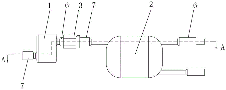
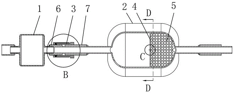
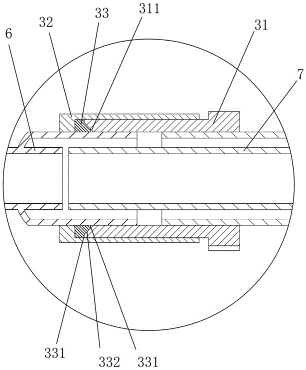
[0023] Such as Figure 1 to Figure 5 As shown, the exhaust gas cooling device of the diffusion furnace in this embodiment includes a primary condensing bottle 1, a secondary condensing bottle 2 and a joint assembly 3, and the inlet joint 7 and the exhaust joint 6 of the primary condensing bottle 1 are separately arranged in the primary condensing bottle 1 and the axes are parallel to each other, the exhaust joint 6 of the primary condensate bottle 1 is connected with the inlet joint 7 of the secondary condensate bottle 2 through the joint assembly 3 . The exhaust gas cooling device of the diffusion furnace adds a first-stage condensing bottle 1 on the basis of the second-stage condensing bottle 2, and the two-stage condensing bottles are connected by a joint assembly 3, and the inlet joint 7 and the exhaust joint 6 of the first-stage ...


PUM


Abstract

The invention discloses a diffusion furnace tail gas cooling device. The diffusion furnace tail gas cooling device comprises a first-stage condensing bottle, a second-stage condensing bottle and a connector assembly; a gas inlet connector and a gas exhausting connector of the first-stage condensing bottle are separately formed in the two ends of the first-stage condensing bottle, and the axes of the gas inlet connector and the gas exhausting connector of the first-stage condensing bottle are parallel with each other; and the gas exhausting connector of the first-stage condensing bottle is connected with a gas inlet connector of the second-stage condensing bottle through the connector assembly. The diffusion furnace tail gas cooling device has the beneficial effects of being simple in structure, adjustable in installing height, capable of properly improving the cooling effect and the like.

Description

technical field [0001] The invention relates to a diffusion furnace, in particular to a cooling device for exhaust gas of a diffusion furnace. Background technique [0002] In order to prevent the poisonous gas and corrosive gas generated during the normal operation of the diffusion furnace from being directly discharged into the air, it is necessary to install a cooling device at the waste outlet of the quartz tube of the diffusion furnace. In the case that the height of the furnace body cabinet and the source cabinet of the diffusion furnace has been determined, the height of the bottle body of the cooling device is limited in a very small range (that is, the radial size / diameter of the bottle body is limited in a very small range ), so that the cooling effect of the cooling device is limited; at the same time, during the installation and commissioning of the cooling device, since the positioning height of the diffusion furnace body is not necessarily the same, the install...

Claims


Application Information

Patent Timeline
Patent Type & Authority Applications(China)
IPC IPC(8): F27D17/00
CPCF27D17/00
Inventor 张弥涛李晔纯张春成李明
Owner HUNAN RED SUN PHOTOELECTRICITY SCI & TECH
Learn More