Tension controlling apparatus for catenary structure equipment

a technology of tension control and catenary structure, which is applied in the direction of mechanical equipment, cables, cables for vehicles/pulleys, etc., can solve the problems of difficult to change the position of the raceway, the separation of the raceway, etc., and achieve the effect of preventing safety accidents and being easy to conn

Active Publication Date: 2018-08-02
KIM SUNG CHAN
View PDF0 Cites 0 Cited by
  • Summary
  • Abstract
  • Description
  • Claims
  • Application Information

AI Technical Summary

Benefits of technology

[0020]In the tension controlling apparatus for the catenary structure equipment according to the present disclosure, it is possible to adjust the tension of the horizontal wire horizontally arranged between the two main pole units.
[0021]Further, by the turnbuckle unit and the damper unit, the tension of the horizontal wire is adjusted to make the length of the horizontal wire be varied within a predetermined range, and the load applied to the horizontal wire is distributed to fundamentally make the lighting unit be free from shaking and impact.
[0022]Further, by the scale mark provided in the damper unit, it is possible to check the tension of the horizontal wire, to control the stretched extent of the damper spring, and to protect the damper unit and prevent safety accidents.
[0023]Further, by the detailed coupling structure of the turnbuckle unit, it is possible to mechanically and cleanly make the turnbuckle connection member for adjusting the tension of the horizontal wire be moved forward and backward, and to stabilize the coupling between the turnbuckle connection member and the tension adjuster.
[0024]Further, by the detailed coupling structure of the turnbuckle unit, it is possible to make the second main pole unit and the horizontal wire be easily connected, to secure a stable support of the adjustment screw, and to prevent the turnbuckle bracket from being deformed as the adjustment screw is turned.
[0025]Further, by the structure of the branch unit, it is possible to move the turnbuckle unit up and down in the second main pole unit, thereby adjusting the installation height of the horizontal wire.

Problems solved by technology

However, when an earthquake and the like shaking happens, a conventional raceway installation structure cannot absorb such a shaking, and therefore the hanger may be separated from the ceiling or an intense shaking may cause the raceway to be separated from the hanger.
Further, the raceway is coupled according to the positions of the hangers, and it is thus difficult to change a position where the raceway is arranged.

Method used


Image

  • Tension controlling apparatus for catenary structure equipment
  • Tension controlling apparatus for catenary structure equipment
  • Tension controlling apparatus for catenary structure equipment

Examples


Embodiment Construction

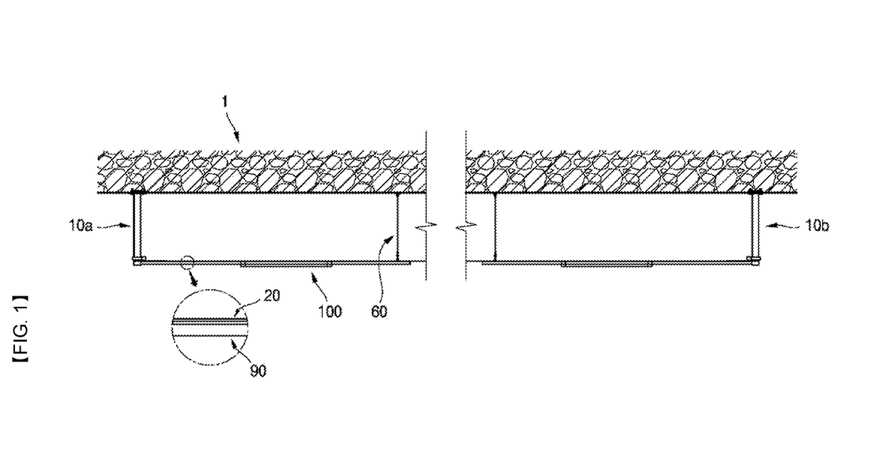
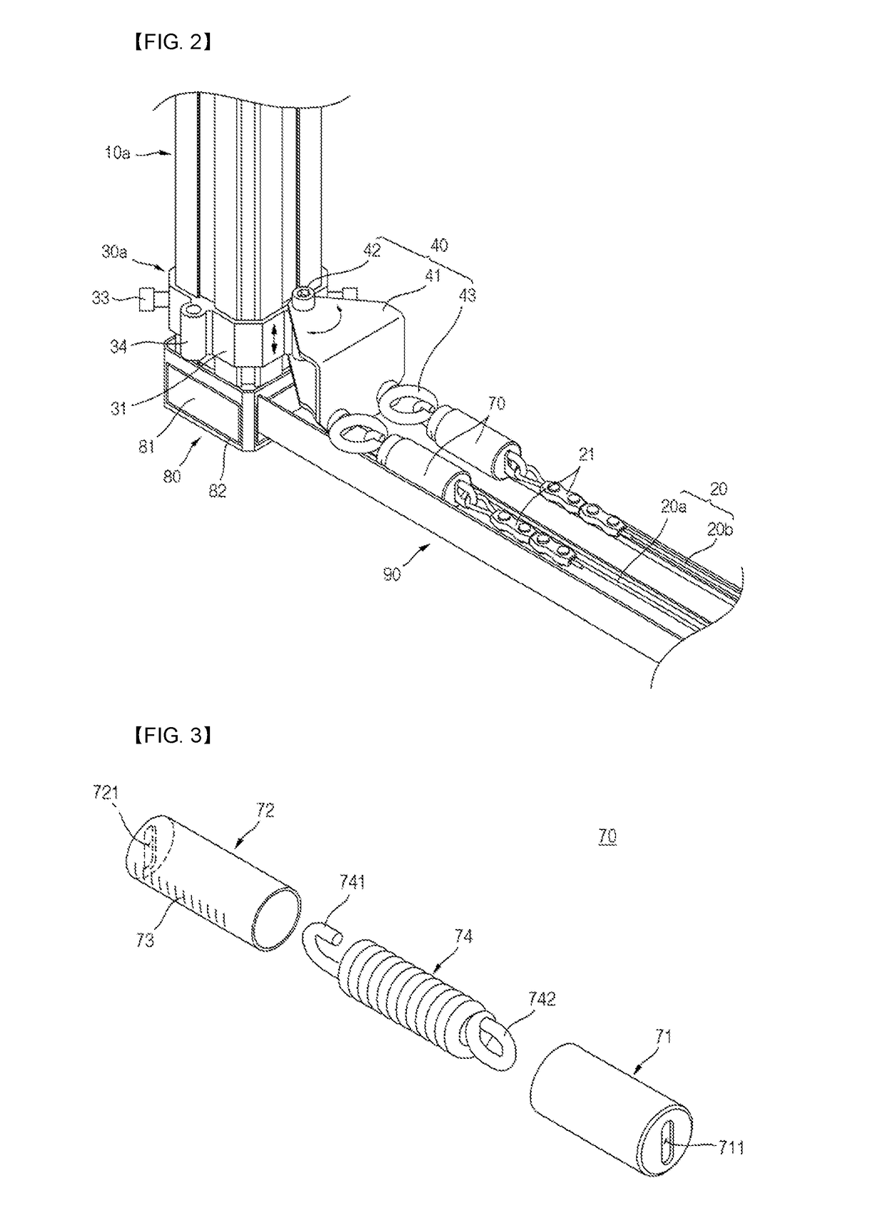
[0039]Hereinafter, embodiments of catenary structure equipment and a construction method of the same according to the present disclosure will be described with reference to the accompanying drawings. Here, the embodiments are not construed as limiting the present disclosure. Further, detailed descriptions about publicly known functions or structures may be omitted to avoid clouding the gist of the present disclosure.

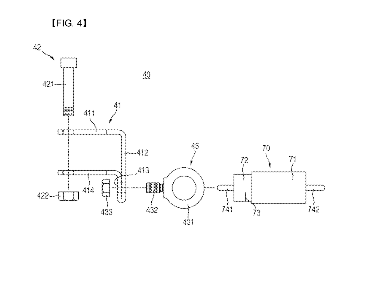
[0040]FIG. 1 is a view of showing catenary structure equipment according to one embodiment of the present disclosure, FIG. 2 is an enlarged perspective view of a portion where a main pole unit, a branch unit, a starter unit, and a horizontal wire are coupled according to one embodiment of the present disclosure, FIG. 3 is a view of showing an alternative example of a damper unit according to one embodiment of the present disclosure, FIG. 4 is an exploded view of the starter unit according to one embodiment of the present disclosure, FIG. 5 is an enlarged perspective view...


PUM


Abstract

Disclosed is a tension controlling apparatus for catenary structure equipment, which can adjust tension of horizontal wires horizontally arranged between two adjacent main pole units.
To this end, a tension controlling apparatus for catenary structure equipment, which adjusts tension of a horizontal wire horizontally arranged between two main pole units installed leaving a certain distance includes a starter unit which is connected to a first main pole unit of the two main pole units, and connects with a first end of the horizontal wire; and a turnbuckle unit which is connected to a second main pole unit of the two main pole units, connects with a second end of the horizontal wire, and adjusts the tension of the horizontal wire.

Description

TECHNICAL FIELD[0001]The present disclosure relates to a tension controlling apparatus for catenary structure equipment, and more particularly to a tension controlling apparatus for catenary structure equipment, which can adjust tension of horizontal wires horizontally arranged between two adjacent main pole units.BACKGROUND ART[0002]In general, a raceway refers to a kind of duct for electric wiring often installed on an exposed ceiling of a parking lot, a machine room or the like in a large concrete structure. The raceway is installed on a floor plate, a wall, a ceiling, etc. as exposed.[0003]For example, a hanger is anchored to an indoor ceiling, and then the raceways are hung on a lower end of the hanger so that the hanger can support the load of the raceways.[0004]However, when an earthquake and the like shaking happens, a conventional raceway installation structure cannot absorb such a shaking, and therefore the hanger may be separated from the ceiling or an intense shaking may...

Claims


Application Information

Patent Timeline
Patent Type & Authority Applications(United States)
IPC IPC(8): F16G11/12H02G1/08
CPCF16G11/12H02G1/081B60M1/26H02G1/04H02G7/02H02G7/053H02G7/20
Inventor CHOI, SE HYUNKIM, JEONG HWANKIM, SUNG CHAN
Owner KIM SUNG CHAN
Why Eureka
Try Eureka