Building robot for brick mortar coating

A construction robot and brick technology, applied in the fields of construction machinery and building decoration, can solve the problems of limited coating thickness and coating area, uneven coating of brick mortar, single application object, etc. Application scenarios, widely used effects

Active Publication Date: 2021-01-26
TSINGHUA UNIV
View PDF12 Cites 0 Cited by
  • Summary
  • Abstract
  • Description
  • Claims
  • Application Information

AI Technical Summary

Problems solved by technology

[0004] In view of the above problems, the present invention provides a construction robot for brick mortar coating, to solve the problems of uneven coating and low efficiency of existing brick mortar coating, and the single application object of the existing trowel machine, coating Problems with thickness and coating area limitations

Method used


Image

  • Building robot for brick mortar coating
  • Building robot for brick mortar coating
  • Building robot for brick mortar coating

Examples


Embodiment 1

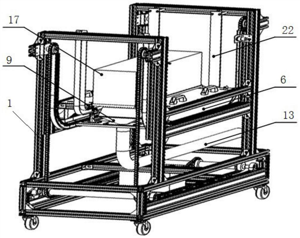
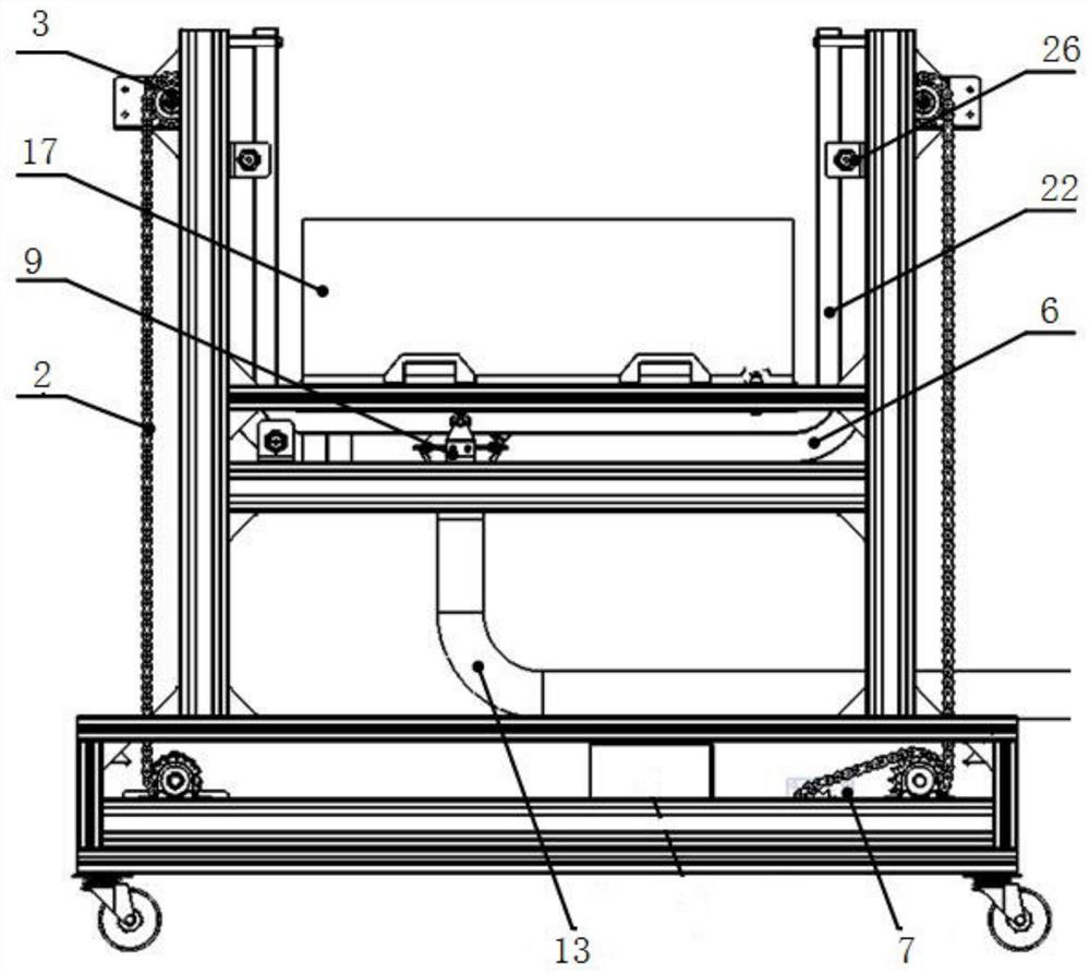
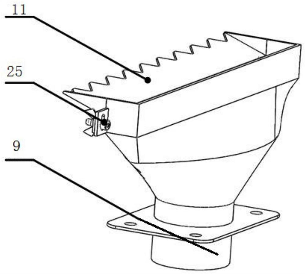
[0023] according to Figure 1-Figure 6 As shown, this embodiment provides a construction robot for brick mortar coating, including a frame 1, a sprocket 3 driving a chain 2 is arranged around the frame 1, two A transmission shaft 4 is connected to the first sprocket 3, and a chain track 6 for installing the conveying pallet 5 is provided in the middle of the frame 1, and the chain 2 around the frame 1 passes through the chain track 6 for circular transmission. One of the transmission shafts 4 is connected with a motor 7, which drives the transmission shaft 4 to rotate, and then drives the chain 2 to move on the sprocket 3 and the chain track 6; the two ends of the conveying pallet 5 are directly connected by the chain side The head 8 is connected to the chain 2 in the chain track, and the middle part of the conveying pallet 5 is fixedly connected with a shower head 9 by bolts. The outer side of the shower head 9 is provided with a protective cover 10, and at the upper end A s...

Embodiment 2

[0034] The working process of a construction robot for brick mortar coating is as follows:

[0035]Step 1: The robot gripper smoothly places the bricks on the positioning plate 16 on the supporting sub-plate of the coating machine. After a delay of 1 second, the photoelectric switch is turned on, and the mortar pumping machine 12 and the coating machine start to work;

[0036] Step 2: The conveying pallet 5 pulls the nozzle 9 to move from one side of the bottom surface of the brick to the other side, and the mortar coating on the bottom surface of the brick is completed so far;

[0037] Step 3: During the turning stage, the mortar pumping machine 12 temporarily stops working, and the delay is about 1 second. When the nozzle 10 quickly turns around the right-angled bend and is completely attached to the side of the brick, the mortar pumping machine 12 continues to work;

[0038] Step 4: When the nozzle 9 moves to the upper edge of the side of the brick, the photoelectric switch...


PUM


Abstract

The invention discloses a building robot for brick mortar coating. The building robot comprises a frame, wherein chain wheels for driving a chain to transmit are arranged on the periphery of the frame, and two chain wheels located at the lower end of the frame are connected with transmission shafts; a chain track for allowing a conveying supporting plate to be arranged is arranged in the middle portion of the frame, chains on the periphery of the frame penetrate through the chain track to carry out cyclic transmission, and one of the transmission shafts is connected with a motor; the two endsof the conveying supporting plate are connected to the chains in the chain track through chain side straight connectors, and the middle portion of the conveying supporting plate is fixedly connected with a spray head through bolts; and a protective cover is arranged on the outer side of the spray head, a scraping plate is arranged on one side of an opening in the upper end of the protective cover,and the spray head is connected with a conveying pipe of a mortar pumping machine. The problems that existing brick mortar coating is uneven, and efficiency is low are solved, and the problems that an existing mortar applying machine is single in application object and limited in coating thickness and coating area are solved.

Description

technical field [0001] The invention relates to the fields of construction machinery, building decoration and the like, in particular to a construction robot used for brick mortar coating. Background technique [0002] At present, in the field of construction, bricklaying is a construction process with a lot of work. Brick plastering is a job with high technical requirements. The traditional method relies on construction workers to pick up bricks with one hand, and with the other hand, mortar is applied to the surface of bricks with a plastering knife and then masonry is carried out. High labor cost, low efficiency and long construction period make it difficult to guarantee the quality of brick coating. [0003] All relate to mortar coating mechanism in the patent of CN 207513207U and CN102672795A, but all there are some shortcomings in these patents. Wherein CN207513207U mentions a kind of brick side plastering machine, can finish the plastering work of whole wall, can't ...

Claims


Application Information

Patent Timeline
Patent Type & Authority Applications(China)
IPC IPC(8): E04G21/22E04G21/20
CPCE04G21/20E04G21/22
Inventor 赵景山李京虎魏松涛纪俊杰张家悦
Owner TSINGHUA UNIV
Why Eureka
Try Eureka