Drilling fluid circulation manifold drilling base pipe clip and installation method thereof

A drilling fluid circulation and drilling rig base technology, applied in the direction of pipes/pipe joints/fittings, pipe supports, mechanical equipment, etc., can solve the problems of damaged drilling fluid circulation manifolds, limited strength of fixed pipe clamps, and non-adjustable height, etc., to achieve Reduced production cost, simple structure, and adjustable installation height

Inactive Publication Date: 2017-08-08
CNPC BOHAI EQUIP MFG
View PDF8 Cites 0 Cited by
  • Summary
  • Abstract
  • Description
  • Claims
  • Application Information

AI Technical Summary

Problems solved by technology

[0002] At present, domestic drilling fluid circulation manifold clamps are roughly divided into two types: the first type uses the ground as a fulcrum to directly support the drilling fluid circulation manifold on the ground. This structure is relatively simple and easy to install. The existing problems are: The height cannot be adjusted, and the fixing is not firm enough. The drilling fluid circulation manifold will vibrate violently during use. Long-term vibration will cause fatigue damage and damage the drilling fluid circulation manifold, and even cause danger.
Moreover, the drilling fluid circulation manifold needs to be disassembled every time the drilling team moves
The second is to install the upper and lower structures of the drilling fluid circulation manifold. The two manifolds are installed on the base of the drilling rig with two sets of fixed pipe clips. The height of this structure is adjustable and the fixation is relatively firm. Vibration during the use of the circulation manifold, but the strength of the fixed pipe clip is limited, and the pipe clip is often broken due to reciprocating vibration

Method used


Image

  • Drilling fluid circulation manifold drilling base pipe clip and installation method thereof

Examples


Embodiment Construction

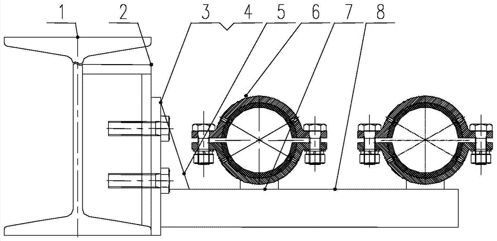
[0024] Attached below figure 1 The structure of the drilling base pipe clip of the drilling fluid circulation manifold described in the present invention is described in detail.

[0025] A drilling fluid circulation manifold drilling base pipe clamp, said drilling fluid circulation manifold drilling rig base pipe clamp includes a support plate 2, an adjustable vertical plate 3, bolts 4, a reinforcement plate 5, a pipe clamp 6 and a support 7; The support plate 2 is welded on the I-beam 1 of the drilling rig base; the adjustable vertical plate 3 is connected with the support plate 2 through the bolt 4; the support 7 is welded on the adjustable vertical plate 3; The reinforcing plate 5 connects the adjustable vertical plate 3 and the support 7 to increase the connection strength between the two, and the tube clip 6 is arranged on the support 7 . The pipe clip 6 is sequentially provided with a guard plate and an elastic backing plate along the radial direction, and the guard pla...


PUM


Abstract

The invention relates to a drilling fluid circulating manifold drilling machine base pipe clamp and an installing method thereof. The drilling fluid circulating manifold drilling machine base pipe clamp comprises a supporting plate, an adjustable vertical plate, bolts, a reinforcing plate, pipe clamp bodies and a support. The supporting plate is welded to drilling machine base i steel. The adjustable vertical plate is connected with the supporting plate through the bolts. The support is welded to the adjustable vertical plate. The reinforcing plate is connected with the adjustable vertical plate and the support to be used for improving connecting strength between the adjustable vertical plate and the support, and the pipe clamp bodies are arranged on the support. The drilling fluid circulating manifold drilling machine base pipe clamp has the advantages of being simple in structure, reasonable in design, convenient and rapid to operate and use, adjustable in installing height, capable of effectively reducing vibration in working and the like.

Description

technical field [0001] The invention relates to the technical field of oil drilling pipe clamps, in particular to a drilling fluid circulation manifold drilling rig base pipe clamp, which is suitable for fixing various drilling fluid circulation manifolds. Background technique [0002] At present, domestic drilling fluid circulation manifold clamps are roughly divided into two types: the first type uses the ground as a fulcrum to directly support the drilling fluid circulation manifold on the ground. This structure is relatively simple and easy to install. The existing problems are: The height cannot be adjusted, and the fixing is not firm enough. The drilling fluid circulation manifold will vibrate violently during use. Long-term vibration will cause fatigue damage and damage the drilling fluid circulation manifold, and even cause danger. Moreover, the drilling fluid circulation manifold needs to be disassembled every time the drilling team moves. The second is to install ...

Claims


Application Information

Patent Timeline
Patent Type & Authority Patents(China)
IPC IPC(8): F16L3/22
CPCF16L3/22
Inventor 王臣聂永坤李志刚廉哲马永恒杨砚航
Owner CNPC BOHAI EQUIP MFG
Why Eureka
Try Eureka