Eureka AIR delivers breakthrough ideas for toughest innovation challenges, trusted by R&D personnel around the world.

A liquid pressure monitoring device and monitoring method

A technology of liquid pressure and monitoring device, applied in the field of sensing, can solve problems such as large blind area of ​​reading, difficulty in meeting explosion-proof requirements in coal mines, and difficulty in reading.

Inactive Publication Date: 2019-08-27
TAIYUAN UNIV OF TECH
View PDF13 Cites 2 Cited by
  • Summary
  • Abstract
  • Description
  • Claims
  • Application Information

AI Technical Summary

Problems solved by technology

[0004] Chinese patent CN86200409 discloses a coal mine explosion-proof digital precision pressure gauge that reads accurate data from a liquid crystal display away from the test point, but due to the single-sided display of the display, the reading blind area is relatively large, resulting in difficult readings; Chinese patent CN204514526U Disclosed is a water pressure measurement device for measuring the water pressure at the underground pipeline of coal mines by rationally arranging hydraulic valves in the flow diversion device and the measurement device, but its structure is not compact and the circuit is complicated; Chinese patent CN201410008882.6 discloses a Bourdon Tube, pressure deformation conversion structure, angle sensor and digital display screen are the main components of the mechanical digital display pressure gauge. CN201210045190.X discloses a bellows pressure gauge that replaces the Bourdon tube with a bellows, and the bellows drives the pointer in the pressure gauge to measure the water pressure through the fork. The instrument is shock-resistant and has a long life. Meters can only be observed at close range

Method used


Image

  • A liquid pressure monitoring device and monitoring method
  • A liquid pressure monitoring device and monitoring method
  • A liquid pressure monitoring device and monitoring method

Examples


Embodiment 1

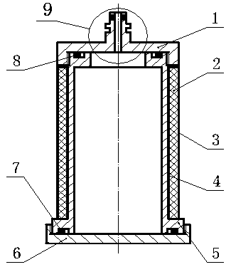
[0065] Such as figure 1 As shown, a liquid pressure monitoring device has a cylindrical structure as a whole. The upper and lower sides of the cylinder are respectively an upper end cover 1 and a lower end cover 6. The upper end cover 1 and the lower end cover 6 are respectively in contact with the middle bearing tube 5. 6 and the inner space formed by the bearing tube 5 is the bearing chamber, and the upper end cover 1, the lower end cover 6 and the bearing tube 5 are respectively connected by threads; the cross sections of the upper end cover 1 and the lower end cover 6 are U-shaped structures, and the bearing tube 5 is a The upper end of the carrying pipe 5 is provided with a concave connector, and the lower end is provided with a convex connector; the top center of the upper end cover 1 is provided with a male direct connector, which is connected with the hydraulic support; the outer side of the bearing pipe 5 is provided with a circular display The color material 2 is pr...


PUM


Abstract

The invention discloses a liquid pressure monitoring device and a monitoring method. The whole device is in a cylindrical structure. Upper and lower end covers are arranged at upper and lower parts of the cylinder. Upper and lower end covers contact a middle bearing tube. An inner space formed by the upper and lower end covers and the bearing tube is a bearing cavity. The upper and lower end covers and the bearing tube are in threaded connection. A male straight joint is arranged at the center of the top of the upper end cover, and is connected with a hydraulic support. A circular color-developing material is arranged on the outer side of the bearing tube. A circular reflective material is arranged between the color-developing material and the bearing tube. A circular polarizing plate is arranged on the outer side of the color-developing material. When the device is used for monitoring, the bearing tube is pressed, and the color-developing material produces circumferential tensile stress. Under the irradiation of a headlight, different colors can be clearly distinguished. Through the corresponding relationship between a color-pressure table, the pressure of the hydraulic support can be monitored. According to the invention, the slump of a roof can be effectively predicted to ensure the safe production of a coal mine.

Description

technical field [0001] The invention relates to a liquid pressure monitoring device and a monitoring method, in particular to a measuring device and a monitoring method for high-pressure liquid pressure in a hydraulic support, belonging to the field of sensing technology. Background technique [0002] There are many occasions in engineering that need to monitor or display liquid pressure, such as the pressure in the hydraulic cylinder, the oil pressure in the oil pipeline, and the pressure of the hydraulic support in the mine, etc. It is very important to be able to display these pressures timely and accurately for the quality assurance of engineering facilities. At present, liquid pressure monitoring devices can be divided into two categories. One type requires power supply facilities. For example, the vibrating wire pressure gauge can convert the pressure of the liquid into the vibration frequency of the steel string and then convert the oil pressure. The digital pressure ...

Claims


Application Information

Patent Timeline
Patent Type & Authority Patents(China)
IPC IPC(8): G01L11/02E21D15/44
Inventor 梁义维赵利平张晓俊蒋雪洋叶美图
Owner TAIYUAN UNIV OF TECH
Why Eureka
Eureka Blog
Learn More