A Rock Shear Loading System
A loading system and rock technology, applied in the direction of applying stable shear force to test the strength of materials, instruments, measuring devices, etc., can solve the problem that the maximum shear loading force cannot reach a higher level, and the manufacturing cost and design cost of the test system increase , The maximum normal loading force and the maximum shearing loading force are difficult to reach a high level at the same time, so as to avoid the sealing problem of the shearing box, increase the maximum shearing loading force, and overcome the restrictive factors
- Summary
- Abstract
- Description
- Claims
- Application Information
AI Technical Summary
Problems solved by technology
Method used
Image

Examples
Embodiment 1
[0044] Type A rock shear loading system, including: a shear box for accommodating rock specimens, and a shear loading system for applying shear force to rock specimens;
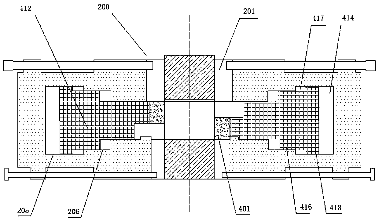
[0045] The shear loading system includes two mutually staggered active loading ends 401 arranged in the shear box 200 to apply shear force to both sides of the rock sample. The active loading ends 401 are controlled by an active hydraulic system, and the active loading ends 401 are The piston chamber used by the hydraulic system to control the force exerted by the active loading end 401 is located inside the shear box, and the oil pipeline of the active hydraulic system passes through the shell of the shear box and is in sealing communication with the piston chamber.
[0046] The piston chamber and indenter part of the shear loading device are directly arranged inside the shear box, which improves the overall stability of the test structure and enables the maximum normal loading force and maximum shear loading...
Embodiment 2
[0051] Type B rock shear loading system, including: a shear box for accommodating rock specimens, and a shear loading system for applying shear force to rock specimens;
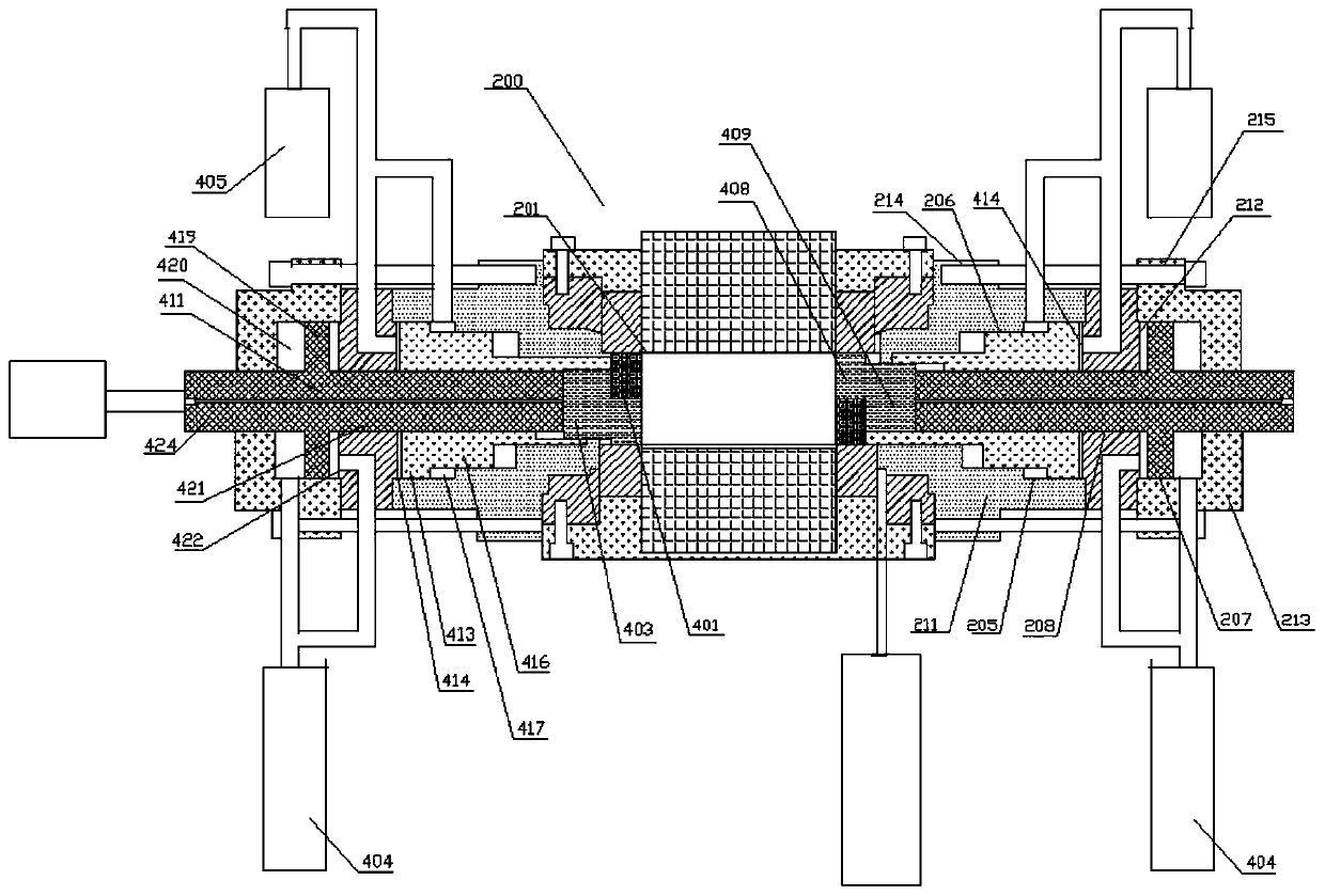
[0052] The shear loading system includes two mutually staggered active loading ends 401 arranged in the shear box 200 to apply shear force to both sides of the rock sample. The active loading ends 401 are controlled by an active hydraulic system 405, The piston chamber used by the active hydraulic system 405 to control the force exerted by the active loading head 401 is located inside the shear box, and the oil pipeline of the active hydraulic system 405 passes through the casing of the shear box and is in sealing communication with the piston chamber.
[0053] The rear end of the active loading head 401 is an active loading shaft 412, the active shaft includes a first active shaft portion 413 with a first diameter, and the side wall of the first active shaft portion 413 is slidably connected with the first ac...
Embodiment 3
[0070] The difference between this embodiment and embodiment one and two is:
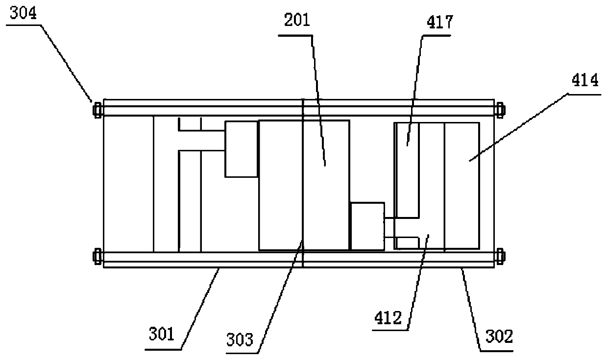
[0071] C-type rock shear loading system, the shear box is divided into a left box body 301 and a right box body 302, the junction of the left box body and the right box body is used as the specimen entrance 303 for placing the rock specimen, and the left and right box bodies There are connecting pieces, specifically, connecting bolts 304 for fixed connection.
[0072]The shearing box includes a box housing part 201 and a shearing loading part for accommodating a shearing loading end and a corresponding piston chamber. The box housing part 201 and the shearing loading part are integrally structured.
[0073] The shear loading part may specifically include an active loading shaft 412 , a first active piston chamber 414 located behind the active loading shaft 412 , and a second active piston chamber 417 located in front of the active loading shaft 412 .
[0074] In the traditional shear box, the shear...
PUM
 Abstract
Description
Claims
Application Information
 - R&D Engineer
- R&D Manager
- IP Professional
- Industry Leading Data Capabilities
- Powerful AI technology
- Patent DNA Extraction
Browse by: Latest US Patents, China's latest patents, Technical Efficacy Thesaurus, Application Domain, Technology Topic.
© 2024 PatSnap. All rights reserved.Legal|Privacy policy|Modern Slavery Act Transparency Statement|Sitemap