Confined steel plate structure and construction method of a super high-rise steel plate concrete shear wall

A steel plate shear wall and concrete shear wall technology, which is applied to building structures, walls, building components, etc., can solve the problems of difficult and precise control of the installation position, large deformation of the steel plate shear wall, and inability to adjust the position after connection, etc. To achieve the effect of easy and precise control of the installation position, saving construction costs and saving manpower

Active Publication Date: 2015-11-18
BEIJING LIUJIAN CONSTR GRP
View PDF6 Cites 0 Cited by
  • Summary
  • Abstract
  • Description
  • Claims
  • Application Information

AI Technical Summary

Problems solved by technology

[0004] The purpose of the present invention is to provide a constrained steel plate structure and construction method of a super high-rise steel plate concrete shear wall, to solve the deformation of the steel plate shear wall caused by the welding of the steel plate shear wall and the surrounding structure when the existing steel plate shear wall is installed Larger, and there are technical problems that the installation position is not easy to control accurately, and the position cannot be adjusted after connection

Method used


Image

  • Confined steel plate structure and construction method of a super high-rise steel plate concrete shear wall
  • Confined steel plate structure and construction method of a super high-rise steel plate concrete shear wall
  • Confined steel plate structure and construction method of a super high-rise steel plate concrete shear wall

Examples


Embodiment Construction

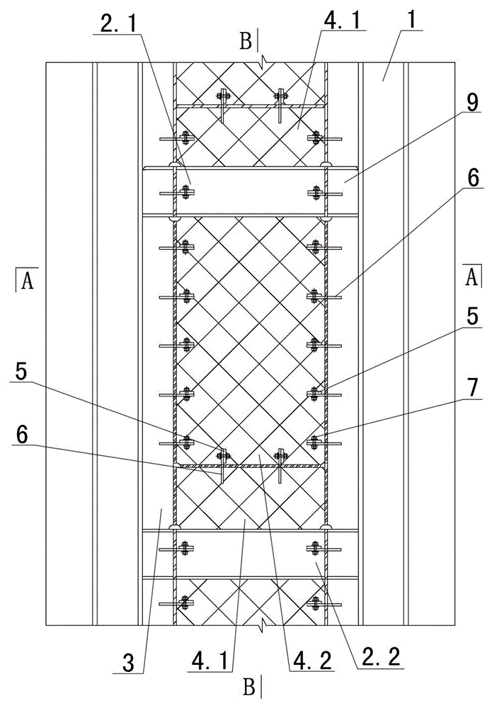
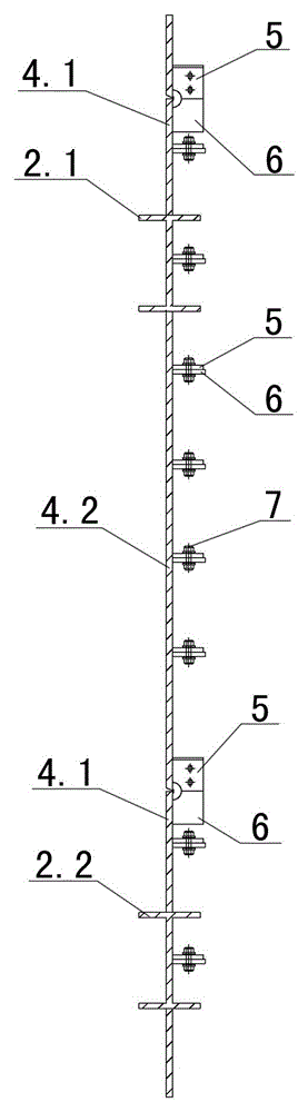
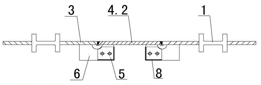
[0033] see example Figure 1-3 As shown in the figure, a constraining steel plate structure of a super high-rise steel plate concrete shear wall includes an outer edge member, a steel plate shear wall 4 connected with the outer edge member, and a constraint connection unit between the two, and the constraint connection unit includes an upper and lower A constraining sub-plate 5 and a constraining mother plate 6 that correspond and cooperate with each other. The constraining sub-plates 5 are arranged at intervals along the inner side of the steel plate shear wall 4, and are perpendicular to the steel plate shear wall. The mother board 6 is arranged at intervals along the inner side of the outer edge member and is perpendicular to the outer edge member, the component size of the restraint sub-board 5 is not larger than the component size of the restraint mother board 6, and the overlapping portion of the two boards is welded by side fillet welding. The joints 8 and the bolts 7 a...


PUM


Abstract

Provided are a constraint steel plate structure of a super high-rise steel plate concrete shear wall and a construction method thereof. The structure comprises an outer edge member, the steel plate shear wall connected with the outer edge member, and a constraint connecting unit between the outer edge member and the steel plate shear wall. The constraint connecting unit comprises constraint daughter boards and constraint mother boards, the constraint daughter boards and the constraint mother boards vertically correspond to each other in a one-to-one mode and are used in cooperation, the constraint daughter boards are arranged along the inner side edge of the steel plate shear wall at intervals and are vertical to the steel plate shear wall, the constraint mother boards are arranged along the inner side edge of the outer edge member at intervals and are vertical to the outer edge member, the member size of the constraint daughter boards is not larger than that of the constraint mother boards, and lap joint coinciding parts of the constraint daughter boards and constraint mother boards are vertically connected through side fillet welds and bolts. The structure solves the technical problems that when an existing steel plate shear wall is installed, the steel plate shear wall highly deforms due to welding between the steel plate shear wall and peripheral structures, and the installation position is not easily controlled accurately and cannot be adjusted after the steel plate shear wall and the peripheral structures are connected.

Description

technical field [0001] The invention relates to a connection structure of a super high-rise steel plate concrete shear wall and a construction method thereof, in particular to a structure in which a super high-rise steel plate concrete shear wall is connected with surrounding structures through restraining steel plates and a construction method thereof. Background technique [0002] At present, most super high-rise building projects are frame core tube structures. In order to meet the lateral pressure resistance of the core tube and the bearing capacity of the structure, steel plate walls are often installed in the core tube wall to meet the stress requirements of the structure. [0003] However, when the steel plate shear wall is installed and constructed at this stage, how to ensure that each steel plate shear wall can be installed smoothly, and the steel plate shear wall after installation has no potential safety hazards. The welding shrinkage deformation of small steel p...

Claims


Application Information

Patent Timeline
Patent Type & Authority Patents(China)
IPC IPC(8): E04B2/56E04B2/58E04B1/61E04G21/14
Inventor 张良张莉莉罗艺吴华张玉品
Owner BEIJING LIUJIAN CONSTR GRP
Why Eureka
Try Eureka