Display device and driving method of display device

A technology of a display device and a driving method, applied in the field of driving, can solve the problems of low light energy, low transmittance of a liquid crystal layer, difficult fingerprint identification, etc., and achieve the effects of improving accuracy, accurate fingerprint identification, and simple method

Active Publication Date: 2017-05-31
BOE TECH GRP CO LTD
View PDF7 Cites 36 Cited by
  • Summary
  • Abstract
  • Description
  • Claims
  • Application Information

AI Technical Summary

Problems solved by technology

[0004] However, in the above-mentioned fingerprint recognition process, due to the low transmittance of the liquid crystal layer, the light energy of the light beam of the backlight in the above-mentioned liquid crystal display that reaches the photoelectric sensor after passing through the liquid crystal layer twice is very low, and the photoelectric sensor only receives A very small part of the light beam diffusely reflected by the finger, and the light energy difference of the divergent light diffusely reflected by the valley and ridge of the fingerprint is extremely small, and there is interference of ambient light between the valleys and ridges of the fingerprint, so The above-mentioned liquid crystal display is difficult to accurately identify fingerprints

Method used


Image

  • Display device and driving method of display device
  • Display device and driving method of display device
  • Display device and driving method of display device

Examples


Embodiment Construction

[0056] Specific embodiments of the present invention will be described in detail below in conjunction with the accompanying drawings. It should be understood that the specific embodiments described here are only used to illustrate and explain the present invention, and are not intended to limit the present invention.

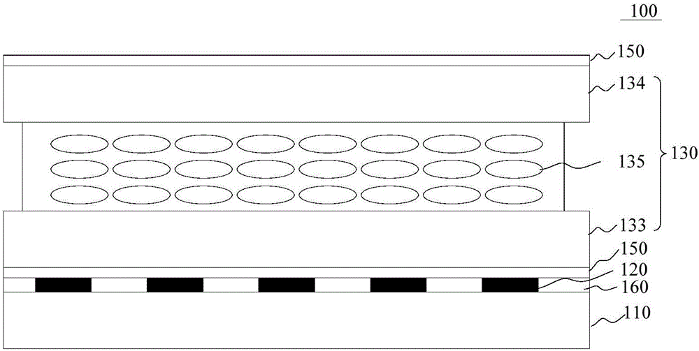
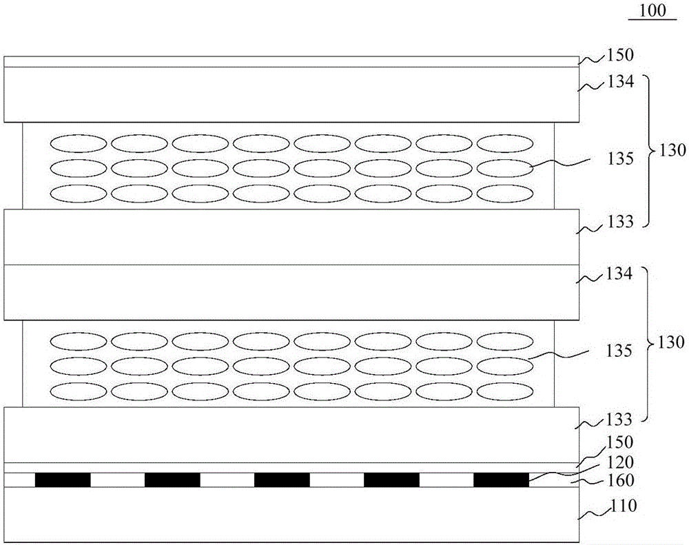
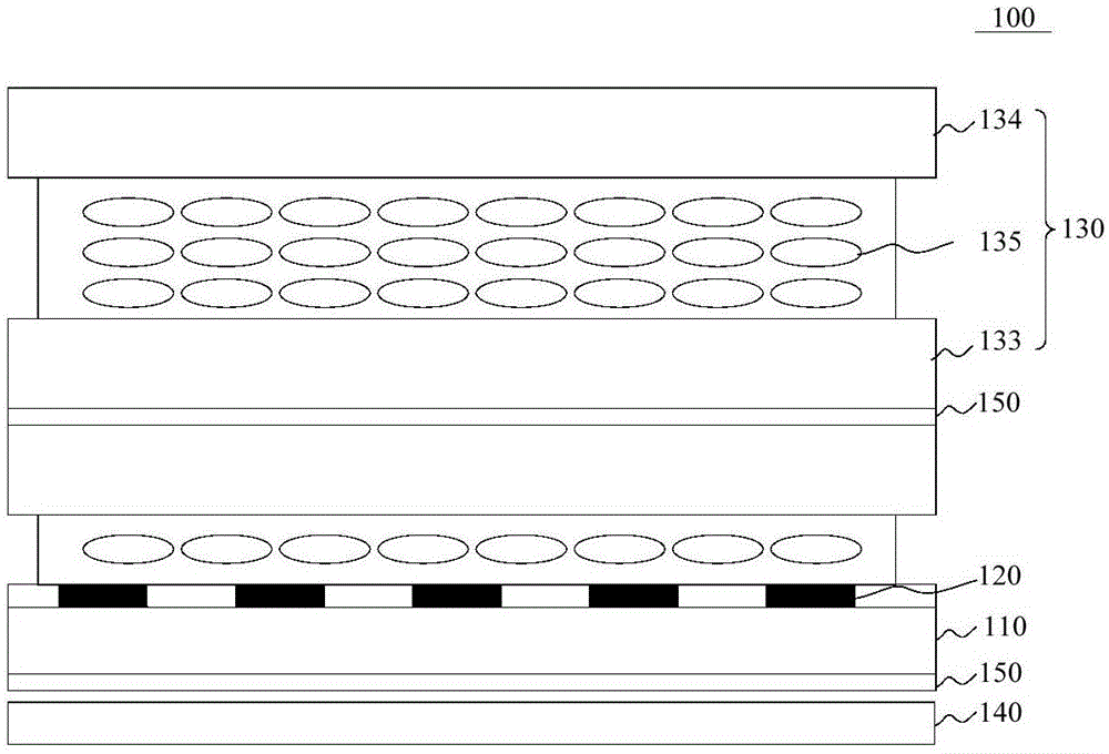
[0057] refer to figure 1 , figure 2 , image 3 , Figure 4 and Figure 6, the first aspect of the present invention relates to a display device 100 . The display device 100 includes a display panel 110, a plurality of photosensitive sensors 120 are arranged at intervals in the display area of ​​the display panel 110, at least one auxiliary panel 130 is arranged on the light emitting side of the display panel 110, and the auxiliary panel 130 can form a plurality of transparent The light area 131, the interval between a plurality of light-transmitting areas 131 forms a light-shielding area 132, and the light emitted by the object F located above the auxiliar...


PUM


Abstract

The invention discloses a display device and a driving method of the display device, and belongs to the technical field of display. The display device comprises a display panel, a display area of the display panel is provided with multiple photosensitive sensors at intervals, a light output side of the display panel is provided with at least one auxiliary panel, the auxiliary panels can form multiple photic areas arranged at intervals, the spacings among the multiple photic areas forms a shade area, and light emitted by an object located above the auxiliary panel can form an image of the object on the photosensitive sensor through the photic area. According to the display device, there is no need to independently set a recognition area for an object recognition (finger recognition) module, object recognition can be achieved directly at the display area of the display device, thus narrow border design can be achieved, and the cost is saved. Meanwhile, when the photic area is utilized to image, light outwards emitted around an object area can be absorbed by the shade area, therefore interference light can be reduced, and thus the accuracy of the object recognition can be improved.

Description

technical field [0001] The present invention relates to the field of display technology, in particular to a display device and a driving method including the display device. Background technique [0002] Generally, with the development of fingerprint recognition technology, it has been widely used in many fields, for example, mobile phones, tablet computers and TVs in electronic equipment terminals; access control and safes in security protection systems, etc. The traditional methods of fingerprint collection mainly include optical, capacitive and ultrasonic imaging technologies. Among them, the optical fingerprint recognition technology has a relatively large recognition range and relatively low cost. Therefore, the optical fingerprint recognition technology has a relatively large application range. wide. [0003] At present, the optical fingerprint recognition technology used in mobile terminals such as liquid crystal displays, including mobile phones, works as follows: a...

Claims


Application Information

Patent Timeline
IPC IPC(8): G02F1/1335G02F1/133
CPCG02F1/13306G02F1/133512G02F1/29G02F1/1347G02F1/13312G02B30/27G06V40/1318H10K59/60H10K59/126G02F2201/16G02F2201/44G09G3/3208G09G3/3611G09G2300/023H10K59/50
Inventor 谭纪风陈小川
Owner BOE TECH GRP CO LTD
Why Eureka
Try Eureka