Positioning module and robot having the same

A positioning module and robot technology, applied in the field of robotics, can solve the problems of occupying too many system resources, affecting the positioning function of the robot lawn mower, and difficult to identify interference light, and achieve the effect of reducing interference light

Pending Publication Date: 2018-04-20
SUZHOU CLEVA PRECISION MACHINERY & TECH
View PDF11 Cites 0 Cited by
  • Summary
  • Abstract
  • Description
  • Claims
  • Application Information

AI Technical Summary

Problems solved by technology

[0003] Taking the lawn mowing robot as an example, when the lawn mowing robot works outdoors, due to the relatively complex and changeable working environment, there are many external interference light sources, which makes the laser locator easy to receive external interference light, which seriously affects the normal operation of the laser locator. And then affect the positioning function of the robot lawn mower
[0004] The existing technology can reduce the influence of interfering light to a certain extent through software filtering, but it takes up more system resources, it is difficult to identify various interfering lights, and misidentification often occurs

Method used


Image

  • Positioning module and robot having the same
  • Positioning module and robot having the same
  • Positioning module and robot having the same

Examples


Embodiment 1

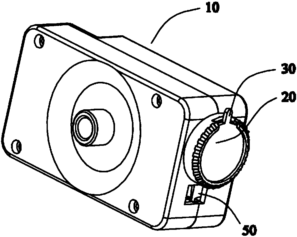
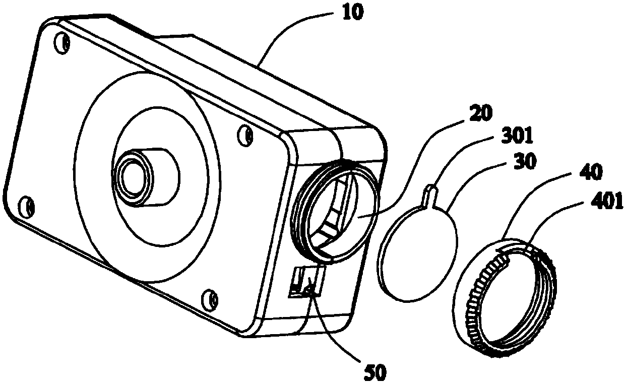
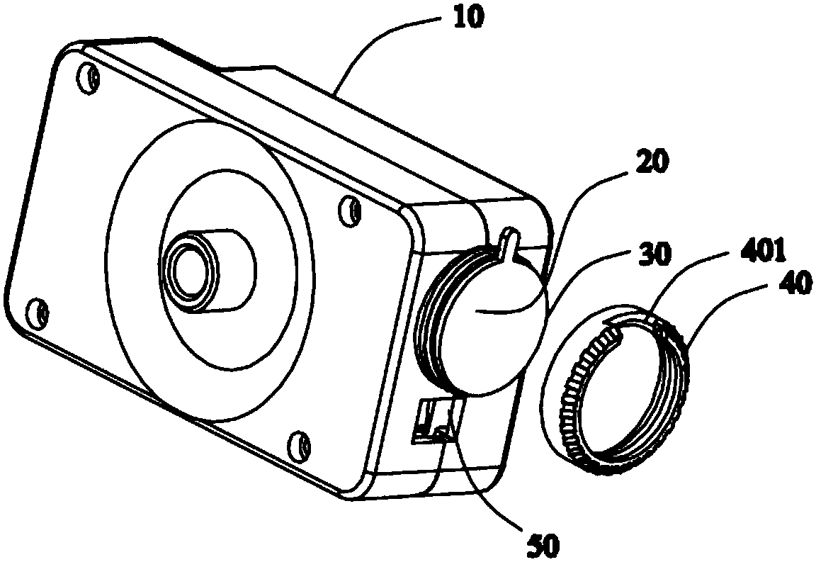
[0041] refer to Figure 1 to Figure 3 , The laser receiving end 20 is set on the laser positioner 10 . The receiving end 20 has a protrusion protruding from the surface of the laser pointer 10 . A polarizer 30 is arranged on the front side of the receiving lens of the receiving end 20 . The polarizer 30 is a lens and may be circular. The polarizer 30 is configured with an adjusting rod 301 for adjusting the polarization direction. The adjustment rod 301 is a rod-shaped protrusion extending radially away from the center of the polarizer 30 , and the adjustment rod 301 is coplanar with the polarizer 30 .

[0042] The polarizer 30 can be placed on the front end of the receiving end 20 and locked by the locking member 40 . The side walls of the locking member 40 form a ring-shaped accommodation cavity, which matches the shape of the polarizer 30 so that the polarizer 30 can be accommodated in the middle of the ring. Several circles of threads are provided on the inside of the...

Embodiment 2

[0048] The difference between this example and Embodiment 1 is that the adjustment rod is a rod-shaped protrusion extending in a direction at an angle to the plane where the polarizer is located, and the adjustment rod is not coplanar with the main body of the polarizer, that is, the adjustment rod is in the same plane as the polarizer. The plane of the main body is raised in an angled direction (not shown).

[0049] The adjustment rod is accommodated in the notch of the locking member, and the distal end of the adjustment rod protrudes outward through the notch to become a force-bearing end when adjusting the polarization direction.

Embodiment 3

[0051] refer to Figure 8 , the housing of the laser positioner 10 is a separate design, and after being fastened together, it can partially surround and form the protrusion of the receiving end 20 . The protruding portion is a cylindrical hollow cavity, matching the shape of the polarizer 30 so that the periphery of the polarizer 30 can be accommodated in the cavity.

[0052] The polarizer 30 is configured with an adjusting rod 301 for adjusting the polarization direction. The adjustment rod 301 is a rod-shaped protrusion extending radially away from the center of the polarizer 30 .

[0053] The casing is provided with a notch 401 for accommodating the adjusting rod 301 . The distance between the farthest end of the adjustment rod 301 and the center of the polarizer 30 is greater than the distance between the far end of the notch 401 and the axis of the protrusion, so that when the polarizer 30 is accommodated in the protrusion, the far end of the adjustment rod 301 passes ...


PUM


Abstract

The invention discloses a positioning module and a robot having the same. The positioning module includes a laser positioner, the laser positioner includes a receiving end for receiving laser having apolarization direction, a polaroid configured at the front side of the receiving end and capable of being arranged to be consistent with the polarization direction of laser, and a locking member through the Polaroid is fixed to the receiving end. The polaroid is equipped with an adjusting part, the locking member or the receiving end are equipped with a gap part, the adjusting part is at least partially accommodated in the gap part, and the adjusting part operably moves along the gap part to change the position of the polaroid relative to the receiving end.

Description

technical field [0001] The invention belongs to the technical field of robots, and in particular relates to a positioning device for a robot that needs to be displaced and positioned automatically. Background technique [0002] More and more robots appear in people's lives, especially some self-propelled robots, which can replace people to perform various tasks. [0003] Taking the lawn mowing robot as an example, when the lawn mowing robot works outdoors, due to the relatively complex and changeable working environment, there are many external interference light sources, which makes the laser locator easy to receive external interference light, which seriously affects the normal operation of the laser locator. Then affect the positioning function of the robot lawn mower. [0004] In the prior art, software filtering can reduce the influence of interfering light to a certain extent, but it takes up a lot of system resources, and it is difficult to identify various interferi...

Claims


Application Information

Patent Timeline
Patent Type & Authority Applications(China)
IPC IPC(8): G01S5/16G02B7/00G02B27/28
CPCG02B7/00G02B27/28G01S5/16G01S17/06
Inventor 孔钊杨赟崔江伟韩奎
Owner SUZHOU CLEVA PRECISION MACHINERY & TECH
Why Eureka
Try Eureka