an optical test chamber

A test chamber, optical technology

Active Publication Date: 2022-07-05
NANJING JUSHA DISPLAY TECH +1
View PDF9 Cites 0 Cited by
  • Summary
  • Abstract
  • Description
  • Claims
  • Application Information

AI Technical Summary

Problems solved by technology

However, when the device is used for tumor research, it is inconvenient to obtain image information of samples from multiple angles, and it cannot automatically switch filters.
[0008] In addition, the existing tumor image capture device still has the problem that the light from the light source cannot evenly irradiate the target object, which affects the effect of fluorescence excitation.

Method used


Image

  • an optical test chamber
  • an optical test chamber
  • an optical test chamber

Examples


Embodiment 1

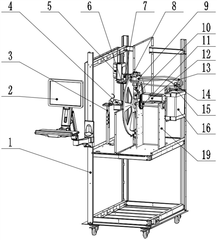
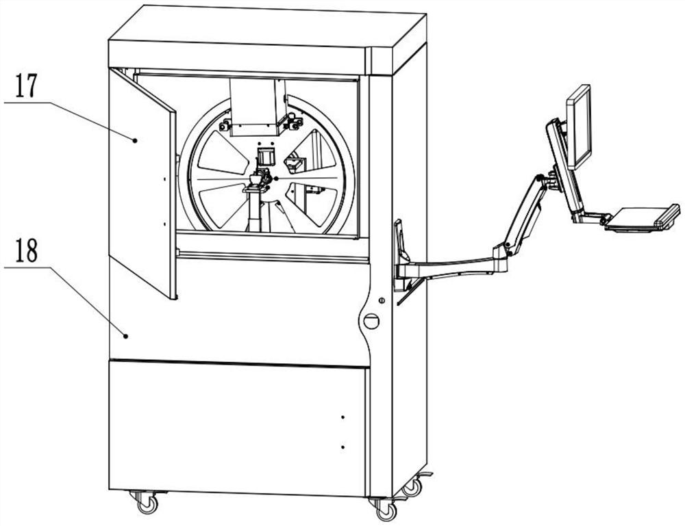
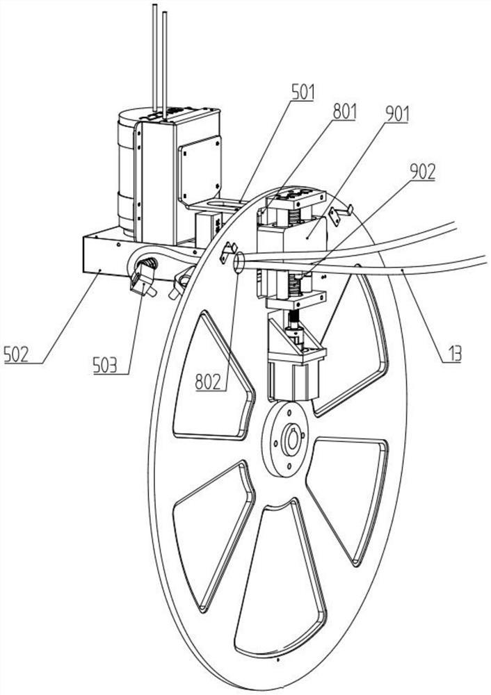
[0039] like Figures 1 to 4 As shown, an optical test box includes a frame 1, an operation door 17, a chassis 18, a control panel 2, a tray 3, a CCD camera 5, a light source 16, a filter wheel, a screw drive mechanism 9, a turntable 8, and a motor.

[0040] The tray 3 is fixed on the rack 1, and the tray 3 is an inverted L shape. When the tumor target 4 is placed on the tray 3, it is generally in anesthetized or dead state. The tray 3 is in a fixed state and has a limiting device, which can assist the positioning and placement of the tumor target 4 and ensure that the tumor target 4 is located at the rotation of the turntable 8. The intersection of the axis and the central axis of the CCD camera 5 does not affect the rotation of the CCD camera at the same time. When shooting, the tumor target is fixed, and the state of the target is the same when shooting in all directions; it is guaranteed to obtain appropriate image information.

[0041] The light source 16 is fixed on the...


PUM


Abstract

The invention provides an optical test box, comprising a frame, a control panel, a tray, a CCD camera, a light source, a filter wheel, a screw drive mechanism, a turntable, and a motor; Filter wheel, CCD camera is fixed on the screw drive mechanism, the screw drive mechanism is fixed on the turntable, the screw drive mechanism and the turntable are driven by the gear motor to rotate for automatic adjustment of the camera distance and angle; the control panel communicates with each other through the control system. The motor is connected to the CCD camera. The present invention realizes automatic control of motor rotation and photography and viewing and storage of captured images through the control panel, the shooting angle and distance of the CCD camera can be automatically and accurately adjusted, and the filter can be automatically switched; When shooting, the target is fixed, the inspection box is closed and a black light-absorbing film is installed inside to reduce the interference of light and ensure the acquisition of appropriate image information.

Description

technical field [0001] The invention belongs to the technical field of medical devices, and in particular relates to an optical test box. Background technique [0002] During tumor research, a fluorescent agent can be injected into the tumor-bearing organism. The fluorescent agent will combine with specific substances in the tumor. The filter can filter out other light and only allow the light of the specified wavelength to pass; after combining the fluorescent agent When the tumor material is irradiated by a light source with a filter, it will be excited by light of a specific wavelength to generate visible light. Using a CCD with a filter to capture the excitation light generated by the tumor-bearing organism, an image with fluorescence indication can be obtained. . [0003] Since tumor research generally requires 360° all-round image acquisition, the commonly used methods at this stage include fixing the tumor target and rotating the fluorescence camera, and fixing the c...

Claims


Application Information

Patent Timeline
Patent Type & Authority Patents(China)
IPC IPC(8): G01N21/64A61B6/00A61B5/00
Inventor 王卫赵启焱
Owner NANJING JUSHA DISPLAY TECH
Why Eureka
Try Eureka