Automatic walking device and automatic walking device positioning system

A technology of automatic walking equipment and laser locator, which is applied in the directions of radio wave measurement system, electromagnetic wave re-radiation, utilization and re-radiation, etc., can solve the problems of misidentification, occupying a lot of system resources, and difficulty in identification of interference light, so as to achieve precise positioning. , the effect of increased discrimination and reduced interference light

Pending Publication Date: 2018-05-11
SUZHOU CLEVA PRECISION MACHINERY & TECH
View PDF7 Cites 0 Cited by
  • Summary
  • Abstract
  • Description
  • Claims
  • Application Information

AI Technical Summary

Problems solved by technology

[0003] Taking the lawn mowing robot as an example, when it works outdoors, due to the relatively complex and changeable working environment, there are many external interference light sources, the laser locator is easy to receive external interference light, which seriously affects the normal operation of the laser locator, and then affects Positioning function of robotic lawn mower
[0004] The existing technology can reduce the influence of interfering light to a certain extent through software filtering, but it takes up more system resources, it is difficult to identify various interfering lights, and misidentification often occurs

Method used


Image

  • Automatic walking device and automatic walking device positioning system
  • Automatic walking device and automatic walking device positioning system
  • Automatic walking device and automatic walking device positioning system

Examples


Embodiment 1

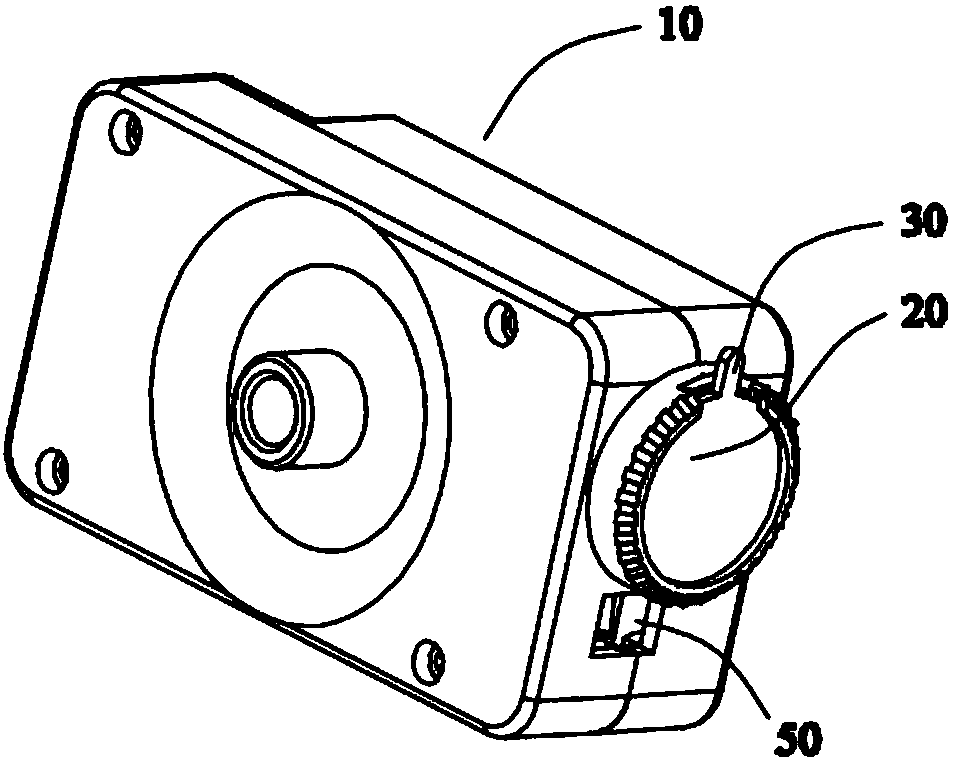
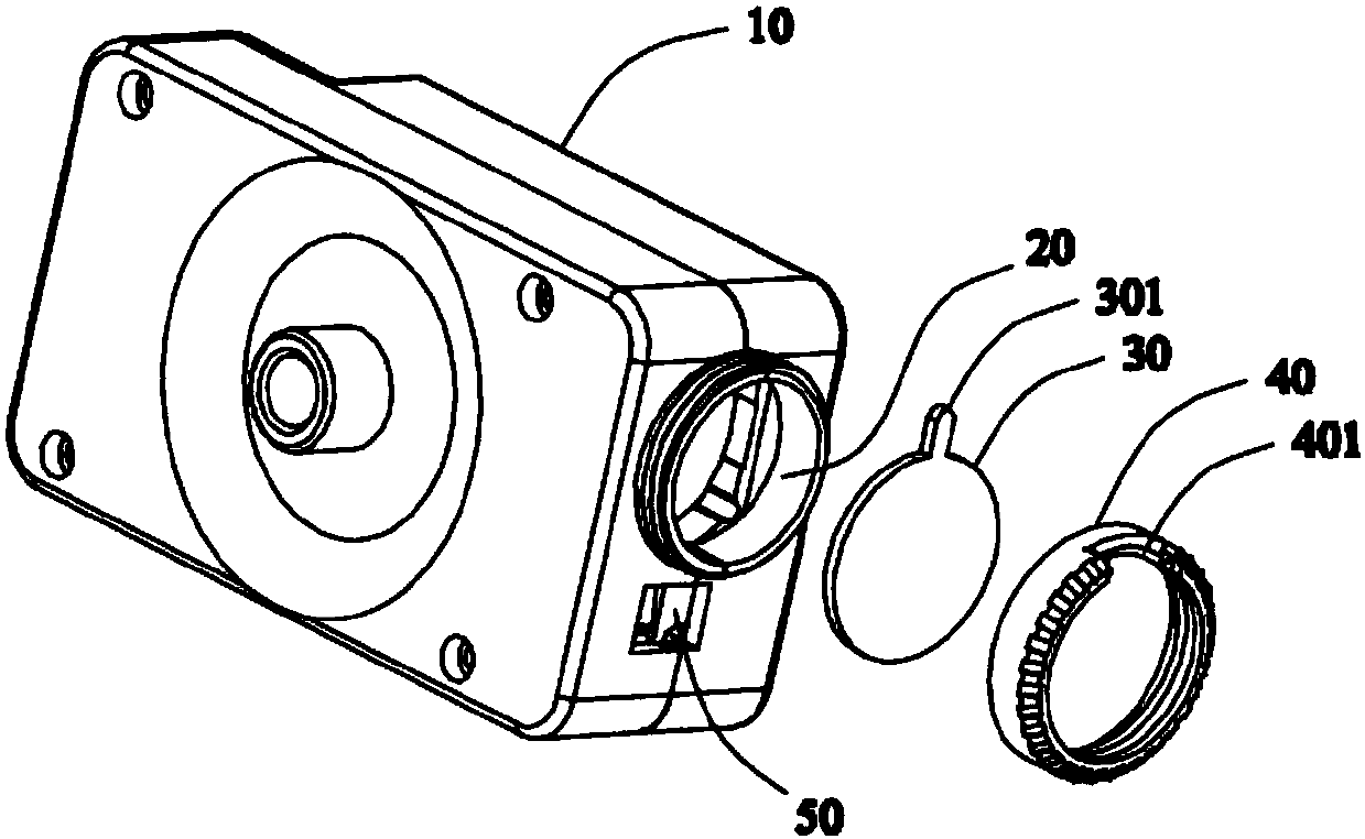
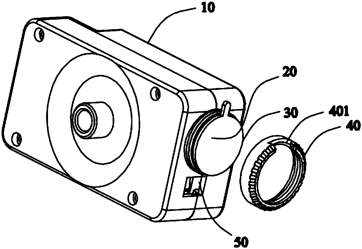
[0040] refer to Figure 1 to Figure 3 , The laser receiving end 20 is set on the laser positioner 10 . The receiving end 20 has a protrusion protruding from the surface of the laser pointer 10 . A polarizer 30 is arranged on the front side of the receiving lens of the receiving end 20 . The polarizer 30 is a lens and may be circular. The polarizer 30 is configured with an adjusting rod 301 for adjusting the polarization direction. The adjustment rod 301 is a rod-shaped protrusion extending radially away from the center of the polarizer 30 , and the adjustment rod 301 is coplanar with the polarizer 30 .

[0041] The polarizer 30 can be placed on the front end of the receiving end 20 and locked by the locking member 40 . The side walls of the locking member 40 form a ring-shaped accommodation cavity, which matches the shape of the polarizer 30 so that the polarizer 30 can be accommodated in the middle of the ring. Several circles of threads are provided on the inside of the...

Embodiment 2

[0046] The difference between this example and Embodiment 1 is that the adjustment rod is a rod-shaped protrusion extending in a direction at an angle to the plane where the polarizer is located, and the adjustment rod is not coplanar with the main body of the polarizer, that is, the adjustment rod is in the same plane as the polarizer. The plane of the main body is raised in an angled direction (not shown).

[0047] The adjustment rod is accommodated in the notch of the locking member, and the distal end of the adjustment rod protrudes outward through the notch to become a force-bearing end when adjusting the polarization direction.

[0048] The present invention adds a polarizer on the front side of the receiving lens to filter out the diffuse reflection light, which achieves the effect of hardware filtering, greatly increases the distinction between effective light and interference light, not only reduces the influence of interference light, but also reduces the The workloa...


PUM


Abstract

The present invention discloses an automatic walking device, an automatic walking device positioning system and an automatic walking device positioning method. The automatic walking device comprises amachine body, a working module connected with the machine body, a walking module and a control module used for coordinating the working module and the walking module. The machine body is also equipped with a laser positioner, and the laser positioner comprises an emission end and a reception end, wherein the laser emitted out by the emission end forms the reflected laser after the reverse reflection, and the reflected laser is received by the reception end; and a polaroid configured at the front side of the reception end and set to be consistent with the polarization direction of the reflected laser, thereby transmitting the reflected laser, and shading the light of different polarization directions.

Description

technical field [0001] The invention relates to an automatic running device, in particular to an automatic running device which needs to automatically walk and work outdoors and a positioning system for the automatic running device. Background technique [0002] More and more smart devices appear in people's lives, especially some smart self-propelled devices, which can replace people to perform various tasks. [0003] Taking the lawn mowing robot as an example, when it works outdoors, due to the relatively complex and changeable working environment, there are many external interference light sources, which makes the laser locator easy to receive external interference light, which seriously affects the normal operation of the laser locator, and then affects Positioning function of a robotic lawnmower. [0004] In the prior art, software filtering can reduce the influence of interfering light to a certain extent, but it takes up a lot of system resources, and it is difficult...

Claims


Application Information

Patent Timeline
Patent Type & Authority Applications(China)
IPC IPC(8): G01S17/06G02B7/00
CPCG02B7/00G02B27/28G01S5/16G01S17/06
Inventor 孔钊杨赟崔江伟韩奎
Owner SUZHOU CLEVA PRECISION MACHINERY & TECH
Why Eureka
Try Eureka