Laser projection system

A laser projection and laser technology, applied in the field of projection display, can solve the problems of degradation of projected image quality, dizziness and discomfort, and reduced user viewing experience, and achieve the effect of improving and eliminating the speckle effect.

Inactive Publication Date: 2017-05-31
HISENSE
View PDF7 Cites 10 Cited by
  • Summary
  • Abstract
  • Description
  • Claims
  • Application Information

AI Technical Summary

Problems solved by technology

[0003] The high coherence of laser also brings the speckle effect in laser projection display. Speckle is that when a coherent light source irradiates a rough object, the scattered light will interfere in space because of its same wavelength and constant phase. Some parts of the space have interference and constructive effects, and some parts have interference and destructive effects. The final result is granular light and dark spots on the screen. These unfocused spots appear to be in a flickering state to the human eye, and are prone to appear after long-term viewing. Dizziness and discomfort will cause the degradation of projected image quality and reduce the user's viewing experience

Method used


Image

  • Laser projection system
  • Laser projection system
  • Laser projection system

Examples


Embodiment 1

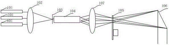
[0047] see Figure 1A , is a schematic diagram of the optical architecture of the laser projection provided by the embodiment of the present application. The optical structure includes: a laser group 101 , a focusing lens 102 , a first phase plate 103 , a uniform light component 104 , a moving diffuser 105 , and a light valve 106 .

[0048] Specifically, the laser group 101 emits a laser beam of at least one color. For simplicity, in this example, the laser group 101 emits a laser beam of one color as an example, which can be a blue laser, or a red laser or a green laser. laser.

[0049] The laser beam spot size emitted by the laser group is usually large. In order to improve the optical utilization of the optical components behind, it is usually necessary to narrow the beam and converge it. Figure 1AIn the figure shown, the focusing lens 102 is an ideal lens, which is only an exemplary description for converging light beams, but in actual product applications, it may be a be...

Embodiment 2

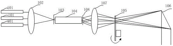
[0085] as a pair Figure 1A The improvement of the laser projection system shown adds that a vibrating reflective phase plate is also provided before the laser beam enters the homogenization part. Specifically, in this application, a vibrating reflective mirror is used to realize the function of a vibrating reflective phase plate to diversify the angle of the light beam, but it is not limited to a vibrating mirror. The role of is not specifically limited, as long as the component can diversify the divergence angle of the light beam.

[0086] like Figure 7 As shown, before the homogenizing component 709, a vibrating mirror 706 is arranged, and the vibrating mirror is driven to vibrate by a driving part at a certain frequency. Movement in the plane), the vibrating mirror changes the position of the light spot incident on the focusing lens through vibration, and then changes the position of the light spot incident on the transmissive fixed diffuser and the uniform light compone...


PUM


Abstract

The invention discloses a laser projection system which comprises a laser light source, a light homogenizing component, a light valve, a first phase plate and a motion diffuser, wherein the laser light source emits laser beams of at least one color; the light homogenizing component, the light valve and the first phase plate are included in a transmission light path of the laser beams; the light homogenizing component is used for receiving and homogenizing the laser beams; the light valve is used for receiving the laser beams homogenized by the light homogenizing component and modulating the laser beams; the first phase plate is arranged on the incident side of the light homogenizing component; the center area of the first phase plate is larger than a divergence angle of the laser beams in a surrounding area; the motion diffuser is arranged on the emergent side of the light homogenizing component and is capable of greatly improving the quantity of generated random phases; the position where the motion diffuser is positioned is conjugated to the light valve surface. Due to the human eye integral actions at the random phases, a spot dissipating effect of a projected picture can be weakened or eliminated to the greatest degree, so that the spot dissipating effect and projected picture display quality are greatly improved.

Description

technical field [0001] The present application relates to the field of projection display, in particular to a laser projection system. Background technique [0002] Laser is a light source with high brightness, strong directionality, and monochromatic coherent light beam. As an excellent coherent light source, laser light source has the advantages of good monochromaticity, strong directionality, and high luminous flux. Projection display technology field. [0003] The high coherence of laser also brings the speckle effect in laser projection display. Speckle is that when a coherent light source irradiates a rough object, the scattered light will interfere in space because of its same wavelength and constant phase. Some parts of the space have interference and constructive effects, and some parts have interference and destructive effects. The final result is granular light and dark spots on the screen. These unfocused spots appear to be in a flickering state to the human eye...

Claims


Application Information

Patent Timeline
Patent Type & Authority Applications(China)
IPC IPC(8): G03B21/20G02B27/48
CPCG03B21/2033G02B27/48G03B21/2013G03B21/206G03B21/208
Inventor 田有良
Owner HISENSE
Why Eureka
Try Eureka