A Rotary Gravity Timing Trigger

A trigger and gravity-type technology, which is applied in the field of rotating gravity-type timing triggers, can solve problems affecting timing effects and other issues

Active Publication Date: 2019-02-22
济南市嬴磊信息科技有限公司
View PDF6 Cites 0 Cited by
  • Summary
  • Abstract
  • Description
  • Claims
  • Application Information

AI Technical Summary

Problems solved by technology

For the two timing technologies mentioned above, the spring timing has a service life because of the deformation of the spring, so the spring timing technology has a certain service life; as for the electronic timing technology, it is limited by power. In some special occasions, if there is no The location of electricity, or the situation of unstable electricity will affect the timing effect

Method used


Image

  • A Rotary Gravity Timing Trigger
  • A Rotary Gravity Timing Trigger
  • A Rotary Gravity Timing Trigger

Examples


Embodiment Construction

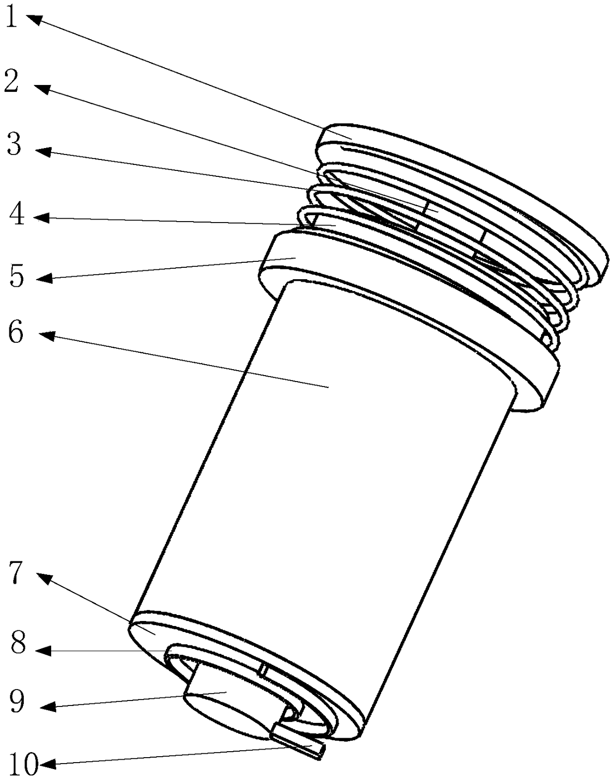
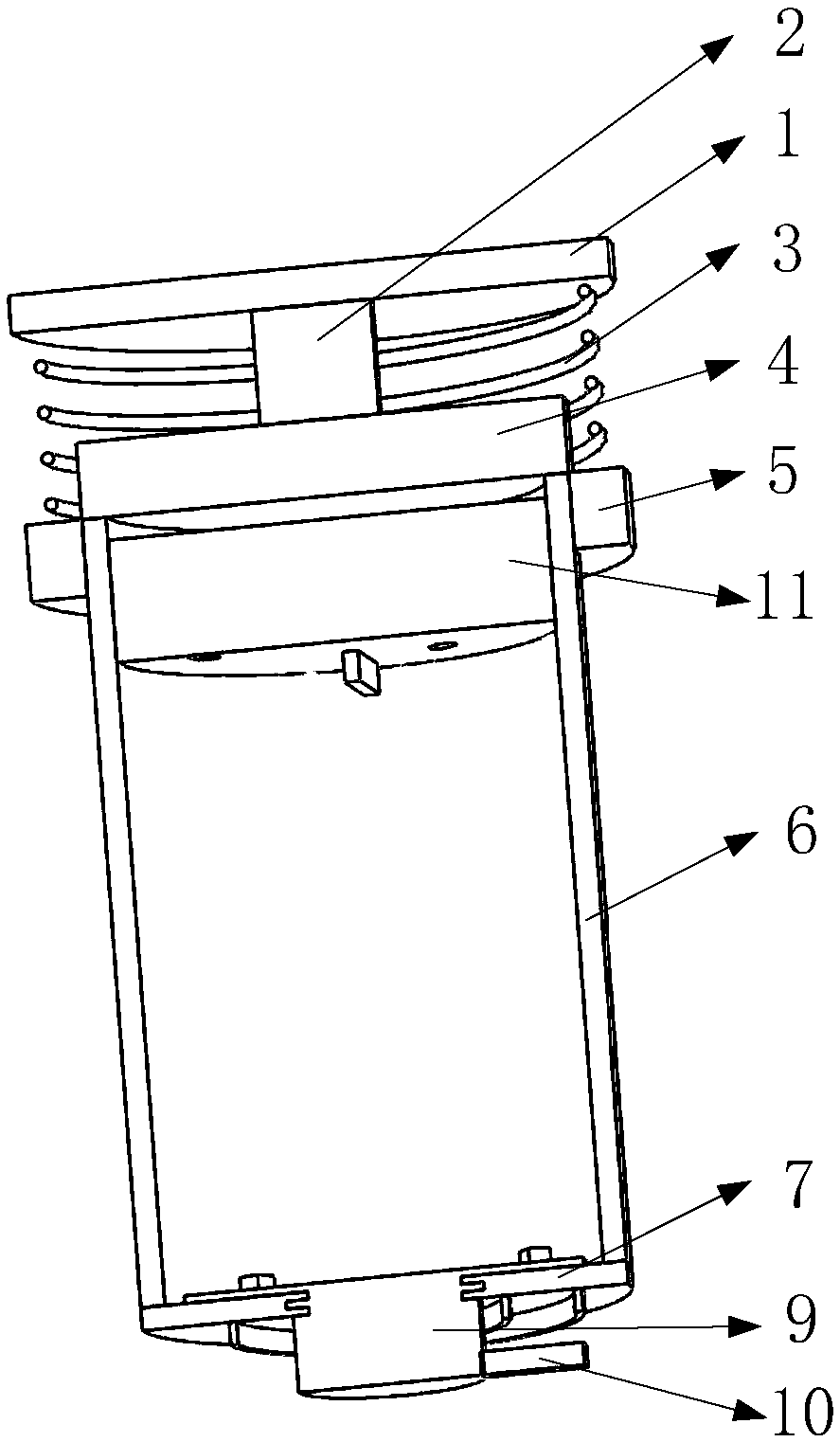
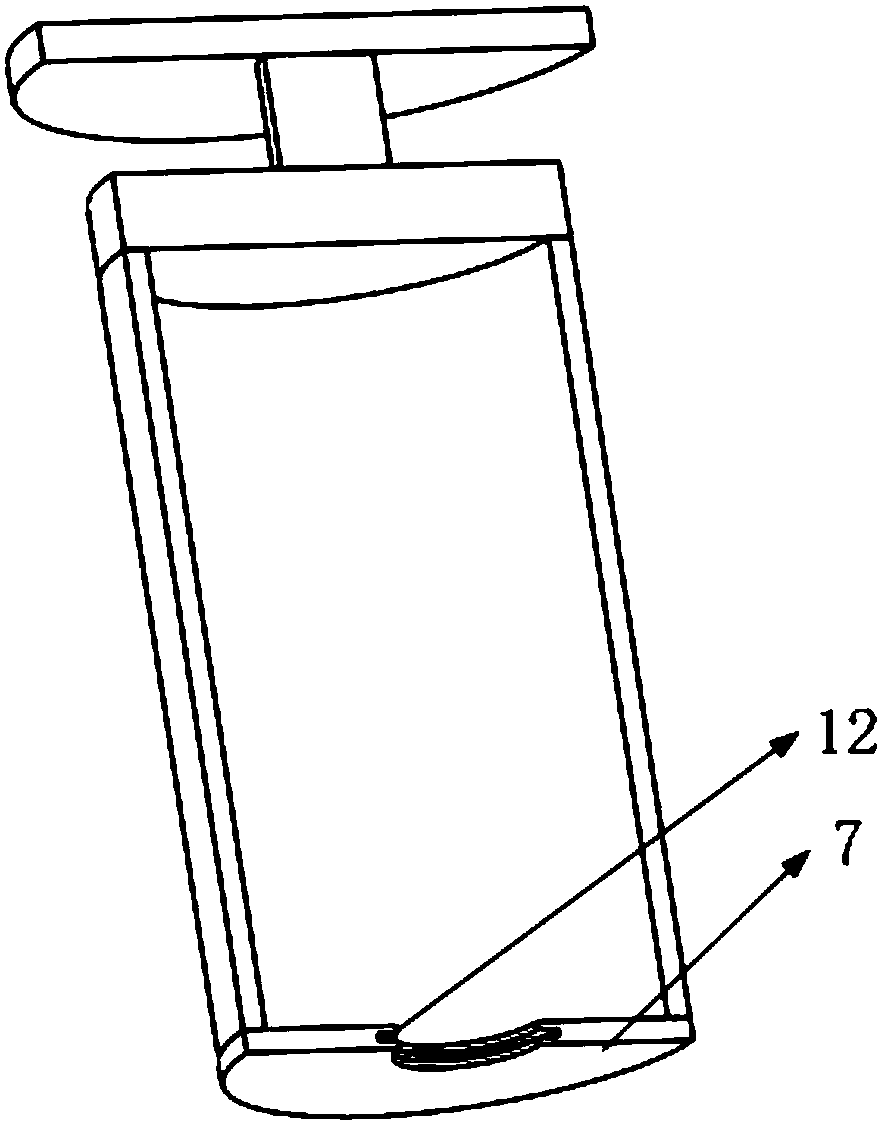
[0023] Such as figure 1 , 2 As shown, it includes support cover, pillar, vibrating spring, top cover, vibrating ring, shell, bottom plate, scroll spring, trigger post, gravity plug, bottom plate groove, among which figure 2 As shown, the top cover is installed on the upper end of the shell, and the gravity plug is installed and slides inside the shell; image 3 As shown, the support cover is installed on the upper side of the top cover through struts, such as figure 1 As shown, the vibration ring is a permanent magnet, and the vibration ring is nested on the outer surface of the housing and slides on the outer surface of the housing. One end of the vibration spring is installed on the bottom of the support cover, and the other end is installed on the upper side of the vibration ring. The side is nested on the outer edge of the top cover; the base plate is installed on the lower side of the housing, and the trigger column is installed on the base plate; the housing is filled...


PUM


Abstract

A rotary gravity-type clocked flip-flop, comprising a vibrating spring (3), a top cover (4), a vibrating ring (5), a shell (6), a bottom plate (7), a spiral spring (8), a triggering post (9) and a gravity stopper (11); the shell (6) has hydraulic oil inside, the gravity stopper (11) has a hydraulic hole (17), the hydraulic oil flows through the hydraulic hole (17) of the gravity stopper (11) when the gravity stopper (11) moves from top to bottom, such that the gravity stopper (11) rotates; when the gravity stopper (11) comes close to the bottom plate (7), a driving shift block (18) will contact and collide with a driven shift block (14), prompting the triggering post (9) to start rotating so as to trigger an external mechanism. The vibrating ring (5) will vertically reciprocate under the effect of an external force when a timer is subjected to vibration, such that the gravity stopper (11) starts moving downward, and timing is started; as the gravity stopper (11) is lubricated and isolated from air by the hydraulic oil, the gravity stopper (11) and the shell (6) would not be oxidized and the accuracy thereof would not be changed, such that the timer has a longer service life; as no electricity is involved, the present invention has a wide application scope and has better usage effect.

Description

Technical field [0001] The invention belongs to the technical field of mechanical timing, in particular to a rotary gravity timing trigger. Background technique [0002] Timing technology From the traditional mechanical spring timing to the most widely used electronic timing technology, timing technology can be described as a wide variety. For the two timing technologies mentioned above, the spring timing has a service life because of the deformation of the spring, so the spring timing technology has a certain service life; as for the electronic timing technology, it is limited by power. In some special occasions, if there is no The location of electricity, or the situation of unstable electricity will affect the timing effect. Therefore, designing a timer that does not use electricity and has a long service life will have certain application prospects. [0003] The present invention designs a rotating gravity timing trigger to solve the above problems. Contents of the i...

Claims


Application Information

Patent Timeline
Patent Type & Authority Patents(China)
IPC IPC(8): G04F1/04
CPCG04F1/04
Inventor 冯林
Owner 济南市嬴磊信息科技有限公司
Why Eureka
Try Eureka