A driving control method and a power circuit

A power supply circuit and output voltage technology, applied in the field of drive control methods and power supply circuits, can solve problems such as large peak-to-peak ripple, reduce voltage ripple peak-to-peak and current ripple peak-to-peak, improve voltage stress and thermal stress, suppress The effect of current overshoot

Active Publication Date: 2019-07-12
HUAWEI DIGITAL POWER TECH CO LTD
View PDF7 Cites 0 Cited by
  • Summary
  • Abstract
  • Description
  • Claims
  • Application Information

AI Technical Summary

Problems solved by technology

[0004] Embodiments of the present invention provide a driving control method and a power supply circuit, which help to solve the problem of large peak-to-peak ripple in burst mode, thereby prolonging the service life of the battery

Method used


Image

  • A driving control method and a power circuit
  • A driving control method and a power circuit
  • A driving control method and a power circuit

Examples


Embodiment Construction

[0040] Embodiments of the present invention will be described below with reference to the drawings in the embodiments of the present invention.

[0041] The embodiment of the invention discloses a driving control method and a power supply circuit, which help to solve the problem of relatively large peak-to-peak value of the ripple in the burst mode, thereby prolonging the service life of the battery. Each will be described in detail below.

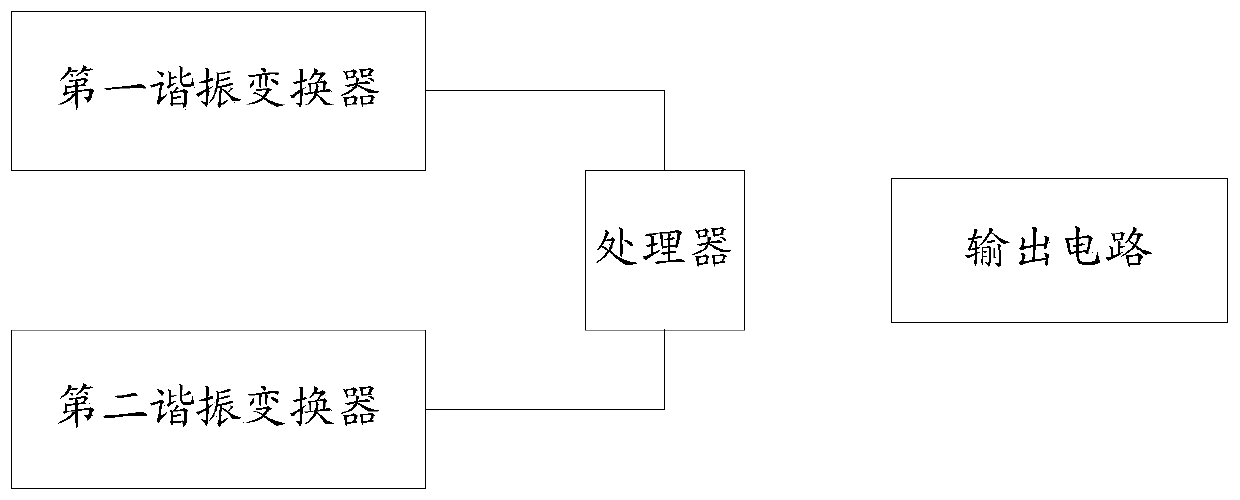
[0042] See figure 2 , figure 2 It is a schematic structural diagram of a power supply circuit provided by an embodiment of the present invention. Such as figure 2 As shown, the power supply circuit includes a processor, a first resonant converter and a second resonant converter. in,

[0043] The processor can be used to start the first driving of the first resonant converter and turn off the second driving of the second resonant converter when the power supply circuit meets the preset condition of alternating waves;

[0044] The p...


PUM


Abstract

The embodiment of the invention discloses a driving control method and a power supply circuit. Wherein, the method includes: when the power supply circuit satisfies the preset alternating wave generating condition, starting the first drive of the first resonant converter, and closing the second drive of the second resonant converter; detecting the start of the first drive Whether the time reaches the preset time threshold; if the preset time threshold is reached, the first drive is turned off and the second drive is turned on. By adopting the embodiment of the present invention, the service life of the battery can be prolonged.

Description

technical field [0001] The present application relates to the technical field of automatic control, in particular to a driving control method and a power supply circuit. Background technique [0002] At present, power circuits generally have the problems of large output power and high power density. Therefore, in order to improve the charging efficiency and heat dissipation effect of power circuits, most high-power and high-density power circuits adopt power factor correction (English: Power Factor Correction) , Abbreviation: PFC) + dual LLC topology receiving. The use of dual-channel LLC topology often results in higher voltage or current, and at this time the power supply circuit will enter a burst (hiccup) mode to achieve a lower output voltage or current. [0003] However, at present, the mainstream wave generation mechanism of the dual LLC topology is positive and negative bus LLC, that is, dual LLC synchronous drive, which causes a large increase in output voltage rip...

Claims


Application Information

Patent Timeline
Patent Type & Authority Patents(China)
IPC IPC(8): H02M1/14H02M1/32
CPCH02M1/14H02M1/32H02M1/0003
Inventor 郭明曾滔王少华
Owner HUAWEI DIGITAL POWER TECH CO LTD
Why Eureka
Try Eureka