Substation optical communication design method and device

A design method and optical communication technology, applied in the field of optical communication, can solve problems such as error-prone

Active Publication Date: 2017-05-31
STATE GRID CORP OF CHINA +2
View PDF5 Cites 1 Cited by
  • Summary
  • Abstract
  • Description
  • Claims
  • Application Information

AI Technical Summary

Problems solved by technology

[0003] In view of this, the embodiment of the present invention provides a substation optical communic

Method used


Image

  • Substation optical communication design method and device
  • Substation optical communication design method and device
  • Substation optical communication design method and device

Examples


Embodiment 1

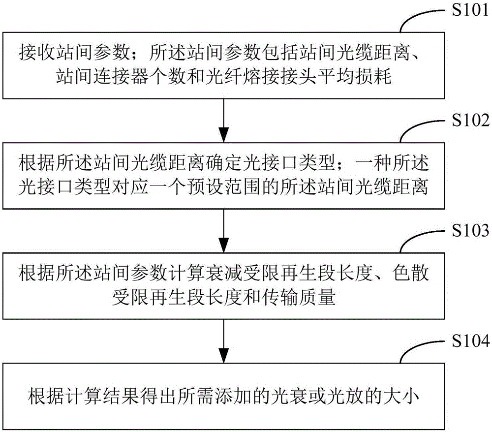
[0078] figure 1 The implementation flow of the substation optical communication design method provided by Embodiment 1 of the present invention is shown, and the details are as follows:

[0079] Step S101, receiving inter-station parameters.

[0080] Wherein, the inter-station parameters may include substation name, inter-station optical cable distance, number of inter-station connectors and average loss of optical fiber fusion splicing joints. For example, the input function area can be set to receive the inter-substation parameters between two substations input by the user.

[0081] Step S102, determining an optical interface type according to the inter-station optical cable distance.

[0082] Wherein, one type of optical interface corresponds to a preset range of inter-station optical cable distances. The corresponding relationship between the optical interface type and the inter-station optical cable distance can be obtained according to experiments, and is set as an op...

Embodiment 2

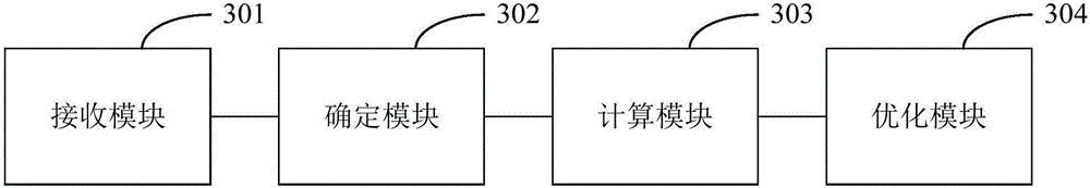
[0129] Corresponding to the substation optical communication design method described in the above embodiments, image 3 A structural block diagram of a substation optical communication design device provided by an embodiment of the present invention is shown. For ease of description, only the parts related to this embodiment are shown.

[0130] refer to image 3 , the device includes a receiving module 301 , a determining module 302 , a calculating module 303 and an optimizing module 304 .

[0131] The receiving module 301 is configured to receive inter-station parameters. The inter-station parameters include the inter-station optical cable distance, the number of inter-station connectors and the average loss of optical fiber fusion splices.

[0132] A determining module 302, configured to determine the optical interface type according to the inter-station optical cable distance. Wherein, one type of optical interface corresponds to a preset range of inter-station optical ...


PUM


Abstract

The invention applies to the technical field of optical communication and provides a substation optical communication design method and device. The method comprises the steps of receiving inter-station parameters, wherein the inter-station parameters comprise inter-station optical cable distance, the number of inter-station connectors and average loss of optical fiber fusion joints; determining optical interface types according to the inter-station optical distance, wherein one optical interface type corresponds to one piece of inter-station optical cable distance in a preset range; calculating an attenuation limited regeneration section length, a dispersion limited regeneration section length and transmission quality according to the inter-station parameters; and outputting an optical attenuation value or an optical amplification value needing to be added according to calculation results. According to the method, the problems that the calculation quantity is high and an error is liable to occur in an optical interface selection calculation process can be effectively solved; functions such as automatically calculating the regeneration section length and automatically generating transmission quality index estimation tables required in a communication design report can be realized; the working efficiency of communication designers of a substation is improved; and the method and the device are widely applied to the optical communication design of the substation.

Description

technical field [0001] The invention belongs to the technical field of optical communication, and in particular relates to a design method and device for optical communication of a substation. Background technique [0002] In the substation communication design process, it is necessary to calculate the length of the attenuation-limited regeneration section of the digital section, the length of the dispersion-limited regeneration section, the optical attenuation and the addition of optical amplifiers, etc. The amount of data required to be calculated in this process is large, and the calculation formula will also change with the length of the optical cable between the two substations. mistake. Contents of the invention [0003] In view of this, an embodiment of the present invention provides a substation optical communication design method and device, so as to solve the problem of error-prone manual calculation in the prior art. [0004] The first aspect of the embodiment...

Claims


Application Information

Patent Timeline
IPC IPC(8): H04B10/079H04B10/293
CPCH04B10/07951H04B10/07955H04B10/2931
Inventor 谢延涛邢琳郝军魁张红梅容春艳吴鹏李宏博庞凝王宁马聪张帅霍晓良
Owner STATE GRID CORP OF CHINA
Why Eureka
Try Eureka