Network protection method, network protection system, controller and equipment

A network protection and controller technology, applied in the field of communication, can solve problems such as business interruption, achieve the effect of solving business interruption and improving reliability

Active Publication Date: 2017-05-31
RAISECOM TECH
View PDF2 Cites 11 Cited by
  • Summary
  • Abstract
  • Description
  • Claims
  • Application Information

AI Technical Summary

Problems solved by technology

[0007] In view of this, the embodiment of the present invention provides a network protection method, system, controller, and equipment to solve the problem of service interruption in the prior art and improve the reliability of the network

Method used


Image

  • Network protection method, network protection system, controller and equipment
  • Network protection method, network protection system, controller and equipment
  • Network protection method, network protection system, controller and equipment

Examples


Embodiment 1

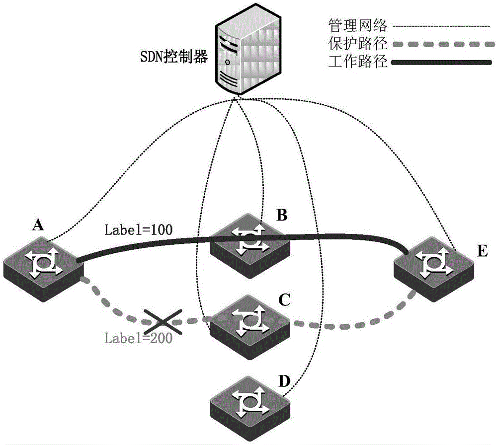
[0103] The first link in Embodiment 1 of the present invention is a protection link.

[0104] The basic configuration steps of the service of the specific embodiment of the present invention are as follows:

[0105] Step 1: The SDN device and the SDN controller establish OpenFlow protocol and netconf protocol connection, each device reports its own resource information, and the reported resource information includes flow table, group table, YANG, etc.;

[0106] Step 2: After the SDN controller and the SDN device are connected, the SDN controller sends and receives LLDP packets through the packet out and packet in messages defined by the OpenFlow protocol to complete the physical topology connection relationship of the SDN device; LLDP packet forwarding and current There are the same technologies, so I won’t repeat them here;

[0107] Step 3: The SDN controller configures Ethernet service extraction on device A through the flow table and group table defined by the OpenFlow pro...

Embodiment 2

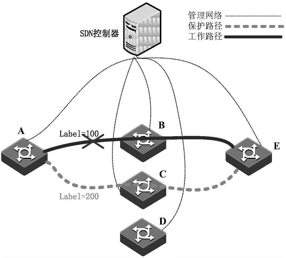
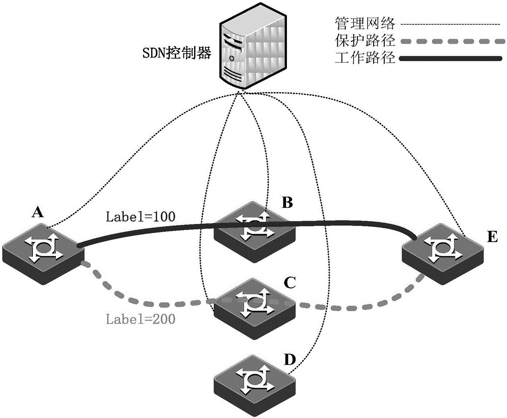
[0126] The first link in Embodiment 2 of the present invention is a working link.

[0127] Such as Figure 10 As shown, the working link A->B->E is the first link of the specific embodiment of the present invention, and the working link A->D->E is the second link created by the device of the specific embodiment of the present invention. When After the working link A->B->E fails, both device A and device E will detect the link interruption alarm information on the working link A->B->E path, and report the alarm information to At the same time, the service will be switched to the protection link A->C->E immediately, and the path switching status will be reported to the controller through netconf. The controller will re-allocate resources and issue a link with a link diagnosis mechanism to the device. Flow table configuration, the device creates a new working link A->D->E according to the link flow table configuration, after that, the controller controls the device to delete the...


PUM


Abstract

The invention discloses a network protection method, a network protection method system, a controller and equipment, which are used for solving the problem of service interruption in the prior art and improving the network reliability. The network protection method comprises the following steps that the controller receives first warning information reported by the equipment in a network, and determines that cable fracture occurs in a first link; the controller issues link flow table configuration with a link diagnosis mechanism to the equipment until first feedback information sent by the equipment is received or second warning information sent by the equipment is received after preset time, wherein the first feedback information is reported to the controller after the equipment creates a second link according to the received link flow table configuration, the controller determines information that the second link is available, and the second warning information is information that the second link is unavailable and is determined by the controller; after receiving the first feedback information, the controller sends a flow table instruction, wherein the flow table instruction is used for controlling the equipment to replace the first link with the second link, to remove the first link and to add the second link into an original protection group.

Description

technical field [0001] The present invention relates to the field of communication technology, in particular to a network protection method, system, controller and equipment. Background technique [0002] As a new type of network architecture, Software Defined Network (SDN) is the core of which is the separation of forwarding and control to achieve centralized control and quick deployment of the network. Under the SDN architecture, the control plane is moved up to the SDN controller, and the SDN device forwards packets according to the instructions of the controller. [0003] In an SDN network that carries services such as inbound private lines, reliability is one of the core indicators for measuring network quality. The larger the network scale and bandwidth, the higher the requirements for network reliability. Among the existing protection technologies, the linear 1:1 protection technology is the most commonly used protection method. In the traditional linear 1:1 protec...

Claims


Application Information

Patent Timeline
Patent Type & Authority Applications(China)
IPC IPC(8): H04L12/707H04L12/703H04L12/741H04L45/24H04L45/28H04L45/74
CPCH04L45/22H04L45/28H04L45/74
Inventor 胡守强焦勇
Owner RAISECOM TECH
Why Eureka
Try Eureka