Air treatment system
An air treatment system, air technology, applied in the direction of air conditioning system, heating and ventilation control system, heating and ventilation safety system, etc., can solve the problem of limited life and other problems, achieve the improvement of aesthetics, accurate filter life calculation, and improve reliability. Effect
- Summary
- Abstract
- Description
- Claims
- Application Information
AI Technical Summary
Problems solved by technology
Method used
Image

Examples
Embodiment Construction
[0078] A. Overview
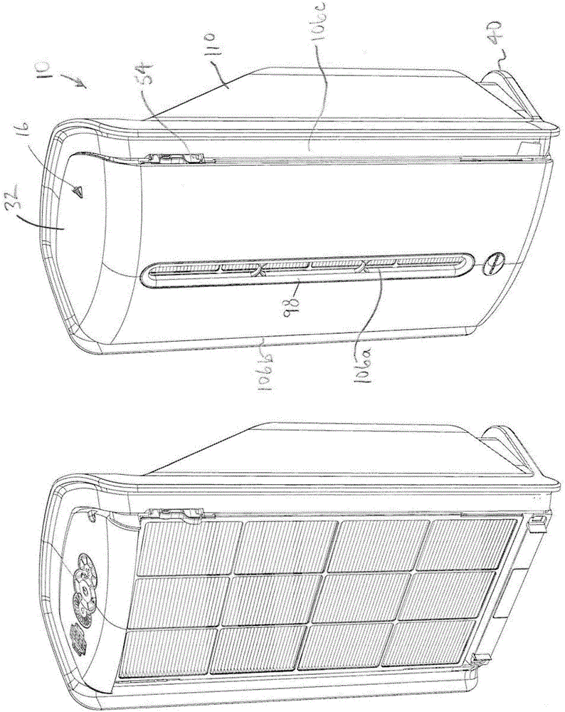
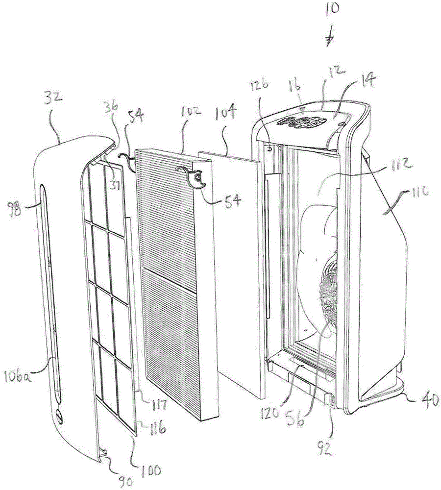
[0079] An air handling system ("ATS") according to an embodiment of the present invention is shown in FIG. 1 . picture The ATS 10 of the illustrated embodiment generally includes a pre-filter 100, a particulate filter 102, and an activated carbon filter 104. The ATS 10 also includes a fan 56 for drawing air into the ATS 10 from the environment, moving the air through the filter, and returning the filtered air to the environment.
[0080] picture The ATS 10 of the illustrated embodiment includes a control system 12 having an electronics module 14 that provides a “dead face” display 16 . The display 16 of this embodiment includes a plurality of display elements 18 that can be selectively illuminated by the control system 12 to provide dynamic content. Some of the display elements 18 may include touch sensors 20 that allow operator input. In this embodiment, the electronics module 14 includes a plurality of light sources 22 , such as LEDs, each uniquely a...
PUM
 Abstract
Description
Claims
Application Information
PatSnap Eureka turns technology decisions into work you can execute. Powered by our Innovation Knowledge Graph, it runs expert workflows across engineering, life sciences, materials and intellectual property. Get your review-ready output in minutes.


