
Mimo-radar measuring method

A MIMO-FMCW, radar target technology, applied in the field of MIMO radar measurement, can solve the problems of high phase difference, cost, code division multiplexing method requirements, and achieve the effect of improving angle estimation and reducing hardware cost

Active Publication Date: 2017-05-31
ROBERT BOSCH GMBH
View PDF6 Cites 27 Cited by
  • Summary
  • Abstract
  • Description
  • Claims
  • Application Information

AI Technical Summary

Problems solved by technology

However, the code division multiplexing method requires high outlay and can only achieve a limited orthogonality of the signals
In frequency division multiplexing, there are the following disadvantages: the phase and Doppler frequency shifts are related to the corresponding wavelength
However, there is the problem that the relative movement of the located object combined with the time difference between the measurements with different switching states leads to phase differences which make subsequent angle estimation difficult

Method used


Image

  • Mimo-radar measuring method
  • Mimo-radar measuring method
  • Mimo-radar measuring method

Examples


Embodiment Construction

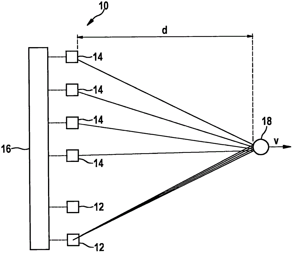
[0063] attached figure 1 The diagram shows a very simple example of a (MIMO) FMCW radar sensor 10 which in this example has only two transmitting antenna elements 12 and four receiving antenna elements 14 . In practice, larger numbers of antenna elements are possible. Transmitting antenna elements 12 are fed by control and evaluation unit 16 and emit radar signals which are reflected on object 18 and received by each of receiving antenna elements 14 . Transmitting antenna elements 12 and receiving antenna elements 14 are each constructed identically and therefore have a consistent line-of-sight. The transmit and receive antenna elements may each consist of a patch antenna array.

[0064] The received signal is down-mixed to a baseband signal and evaluated in the control and evaluation unit 16 . Radar sensor 10 is installed, for example, in a vehicle at the front and serves to measure distance d, angle and relative velocity v of object 18 , for example a vehicle driving ahea...


PUM


Abstract

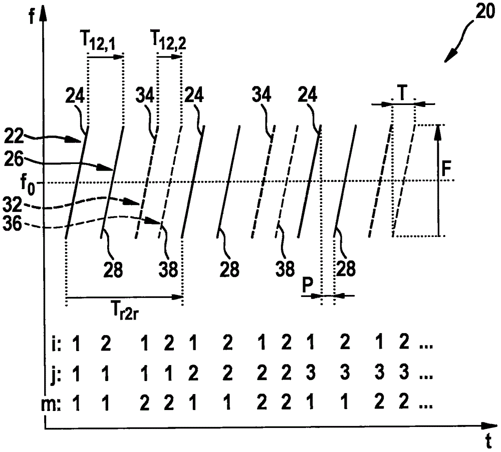
The invention relates to a MIMO-FMCW radar sensor and to a MIMO-time-division multiplexing method for locating a radar target (18), wherein a FMCW radar measurement is carried out using a transmission signal, of which the modulation patterns for different transmission switching states (m), which differ in the selection of antenna elements (12) used for transmitting, comprise time-interleaved sequences (22; 26; 32; 36) of ramps (24; 28; 34; 38); ambiguous values for the relative speed (v) of the radar target (18) are determined from a position (k, l) of a peak in a two-dimensional spectrum (56); phase relationships between spectral values of spectra (X) are checked for conformity with the phase relationships (a (v,m)) expected for a plurality of the determined values of the relative speed (v); based on said phase relationships, from the determined periodic values of the relative speed (v), an estimated value for the relative speed (v) of the radar target (18) is selected; and based on amplitudes and / or phase relationships between obtained base band signals (b), the angle of the radar target (18) is determined.

Description

technical field [0001] The invention relates to a method for locating radar targets by means of an angle-resolved MIMO-FMCW radar sensor, wherein the received signal is down-mixed with the transmitted signal to a baseband signal and according to the use of the radar sensor The amplitude and / or phase relationship between the baseband signals obtained with different choices of transmitted and received antenna elements determines the angle of the located radar target. [0002] The invention also relates to a radar sensor, in particular for a motor vehicle, which is designed to carry out the method. Background technique [0003] FMCM radar sensors are used in motor vehicles for detecting the traffic environment, especially for locating other vehicles. The positioning results can be used for various assistance functions, for example for automatic distance adjustment, automatic collision warning or also for automatically triggering emergency braking in the event of a severe colli...

Claims


Application Information

Patent Timeline
Patent Type & Authority Applications(China)
IPC IPC(8): G01S7/35G01S13/34G01S13/42G01S13/58G01S13/931
CPCG01S7/354G01S13/343G01S13/42G01S13/536G01S13/584G01S13/931G01S2013/0245G01S13/34G01S7/356G01S13/0209
Inventor B·勒施M·朔尔
Owner ROBERT BOSCH GMBH
Learn More