
Device for blending material for coating inner cavity of flow control valve

A flow control valve and inner cavity technology, which is applied in the field of flow control valve inner cavity coating material blending equipment, can solve problems such as insufficient stirring

Inactive Publication Date: 2017-06-06
采泉
View PDF3 Cites 7 Cited by
  • Summary
  • Abstract
  • Description
  • Claims
  • Application Information

AI Technical Summary

Problems solved by technology

[0006] In order to overcome the shortcomings of insufficient stirring in the prior art, the technical problem to be solved by the present invention is to provide a fully stirred flow control valve cavity coating material blending equipment

Method used


Image

  • Device for blending material for coating inner cavity of flow control valve
  • Device for blending material for coating inner cavity of flow control valve
  • Device for blending material for coating inner cavity of flow control valve

Examples


Embodiment 1

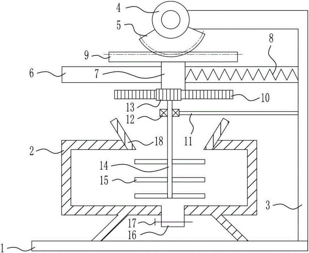
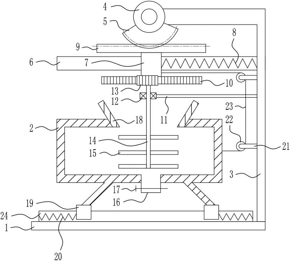
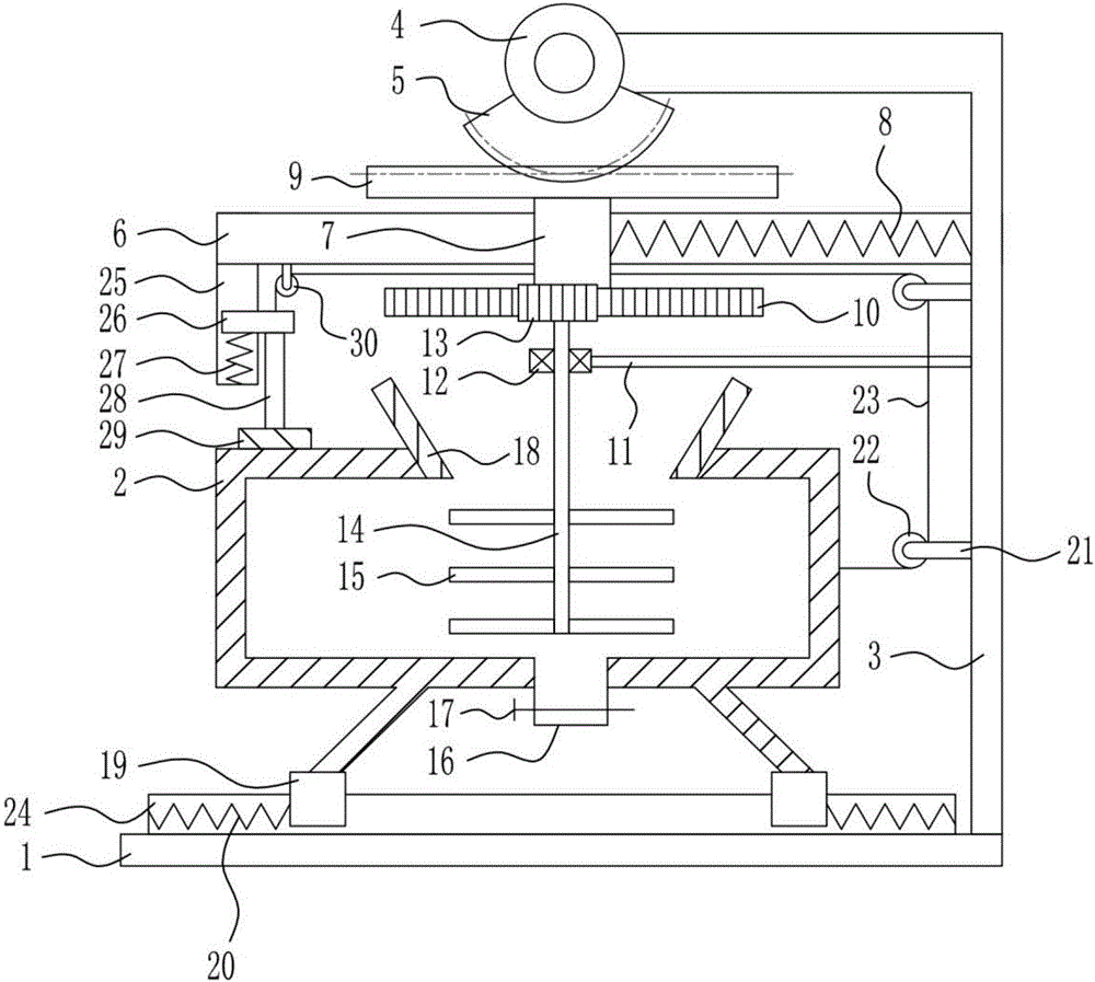
[0025] A flow control valve inner cavity coating materials blending equipment, such as Figure 1-3 As shown, it includes a base 1, a distribution box 2, a right frame 3, a motor 4, a sector gear 5, a first slide rail 6, a first slider 7, a first spring 8, a first rack 9, and a second rack 10. The first support rod 11, the bearing seat 12, the first gear 13, the rotating rod 14, the stirring rod 15, the discharge pipe 16, the electric control valve 17 and the feeding hopper 18, and the top of the base 1 is equipped with a blending box 2 for blending The top of the box 2 is provided with a feed hopper 18, the bottom of the mixing box 2 is provided with a discharge pipe 16, and an electric control valve 17 is provided in the discharge pipe 16, and the right frame 3 is provided on the right side of the top of the base 1, and the left side of the top of the right frame 3 Be provided with motor 4, be connected with sector gear 5 on motor 4, be provided with first slide rail 6 on the...


PUM


Abstract

The invention relates to a blending device, in particular to a device for blending a material for coating an inner cavity of a flow control valve. The invention aims at providing a device, which is full in stirring, for blending the material for coating the inner cavity of the flow control valve. In order to achieve the aim, the invention provides the device for blending the material for coating the inner cavity of the flow control valve; the device comprises a base, a blending box, a right frame, a motor, a sector gear, a first sliding rail, a first sliding block, a first spring, a first rack, a second rack, a first support rod, and the like, wherein the blending box is arranged on the top of the base; a feed hopper is arranged on the top of the blending box, and a discharge pipe is arranged at the bottom of the blending box; an electronic control valve is arranged in the discharge pipe; the right frame is arranged at the right side of the top of the base, the motor is arranged at the left side of the top of the right frame, and the sector gear is connected with the motor. The device for blending the material for coating the inner cavity of the flow control valve is provided with the first sliding block which continuously moves left and right, so that the blending box is enabled to move left and right ceaselessly.

Description

technical field [0001] The invention relates to a blending device, in particular to a blending device for coating materials for the inner cavity of a flow control valve. Background technique [0002] The flow control valve is a multi-functional valve that uses high-precision pilot mode to control the flow. It is suitable for pipelines that need to control the flow and pressure of the water distribution pipe, keep the predetermined flow constant, limit the excessive flow to a predetermined value, and appropriately reduce the upstream high pressure, even if the pressure upstream of the main valve changes, it will not affect Flow downstream of the main valve. The connection methods are divided into flange type, threaded type and welding type. The control and adjustment methods are divided into automatic and manual. [0003] Most of the existing blending equipment is not sufficiently stirred, and the production efficiency is low, which affects the production process. [0004...

Claims


Application Information

Patent Timeline
Patent Type & Authority Applications(China)
IPC IPC(8): B01F11/00
CPCB01F31/50B01F31/56
Inventor 采泉
Owner 采泉
Learn More