Sweep collecting structure of machine tool machining

A technology of machine tools and collection tanks, applied in metal processing equipment, metal processing machinery parts, manufacturing tools, etc., can solve the problems of affecting the service life of the cutting machine, increasing the wear of the cutting machine, and easy access to the cutting machine, so as to reduce the difficulty of collection and Artificial work intensity, improve cutting processing efficiency, and reduce the effect of collection difficulty

Inactive Publication Date: 2017-06-06
重庆市木越机械制造有限公司
View PDF0 Cites 3 Cited by
  • Summary
  • Abstract
  • Description
  • Claims
  • Application Information

AI Technical Summary

Problems solved by technology

[0002] When using a cutting machine to cut metal, a lot of metal debris will be splashed. These metal debris not only hurt the human body, but also easily enter the cutting machine, increase the wear of the cutting machine, and affect the service life of the cutting machine; A metal cutting machine tool that can both remove metal chips and collect metal chips for reuse

Method used


Image

  • Sweep collecting structure of machine tool machining

Examples


Embodiment 1

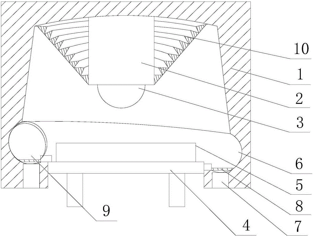
[0020] Such as figure 1 As shown, the present embodiment includes a circular workbench 4, on which a shield cover 1 is installed, the side of the shield cover 1 is provided with an opening for the workpiece 5 to enter and exit, and there is an opening in the shield cover 1 cavity, and an annular collecting tank 6 is arranged at the bottom of the cavity, and the side of the collecting tank 6 is connected to the side wall of the workbench 4, and the telescopic arm 2 moves through the top of the shielding cover 1 and is placed Right above the workbench 4, and at the end of the telescopic arm 2, a cutting wheel 3 is rotated; A sliding block 9 compatible with the collection tank 6 is slidably arranged on one end of the sliding block 9, and traction ropes are respectively connected on both sides of the sliding block 9, and a conical sealing organ is arranged on the inner wall of the top end of the shielding cover. Cover 10, the movable end of the sealed organ cover 10 is connected ...


PUM


Abstract

The invention discloses a sweep collecting structure of machine tool machining. The sweep collecting structure comprises a worktable; a shielding cover is mounted on the worktable; an opening allowing a workpiece to enter and go out is formed in the side of the shielding cover; a cavity is formed in the shielding cover; an annular collecting groove is formed in the bottom of the cavity; and the side of the collecting groove is connected with the side wall of the worktable. A telescopic arm movably penetrates through the top of the shielding cover, and a cutting wheel is rotatably arranged at the tail end of the telescopic arm. A filter screen is mounted on the collecting groove, and a gap is reserved between the filter screen and the bottom of the collecting groove. The collecting groove is arranged obliquely in the circumferential direction of the bottom of the cavity, a sliding block matched with the collecting groove is slidably arranged at the end, in the high position, of the filter screen, and traction ropes are connected on the two sides of the sliding block correspondingly. At the time of cutting, produced metal sweeps start to slide downward along the inner wall of the cavity until falling into the annular collecting groove, and after cutting is finished, the collecting groove can be cleaned by simple tools such as a broom. Meanwhile, the metal sweeps accumulated in the collecting groove are intensively recycled to achieve secondary utilization.

Description

technical field [0001] The invention relates to a processing machine tool, in particular to a machine tool processing waste collection structure. Background technique [0002] When using a cutting machine to cut metal, a lot of metal debris will be splashed. These metal debris not only hurt the human body, but also easily enter the cutting machine, increase the wear of the cutting machine, and affect the service life of the cutting machine; Metal cutting machine tools that can both remove metal chips and collect metal chips for reuse appear. Contents of the invention [0003] The purpose of the present invention is to provide a machine tool processing waste collection structure, which facilitates the comprehensive collection of metal scraps and realizes the purpose of repeated utilization. [0004] The object of the present invention is achieved through the following technical solutions: [0005] A machine tool processing waste collection structure, including a circular ...

Claims


Application Information

Patent Timeline
Patent Type & Authority Applications(China)
IPC IPC(8): B23Q11/00B23Q11/08
CPCB23Q11/0042B23Q11/0816Y02P70/10
Inventor 许伟
Owner 重庆市木越机械制造有限公司
Why Eureka
Try Eureka