Chipping-blocking mechanism used for metal plate machining

A metal plate and workbench technology, applied in metal processing machinery parts, metal processing equipment, manufacturing tools, etc., can solve problems such as affecting the service life of the cutting machine, increasing the wear and tear of the cutting machine, and harming the human body, so as to reduce the difficulty of collection and Manual work intensity, provide cutting efficiency, and avoid the effect of processing environmental pollution

Inactive Publication Date: 2017-06-06
重庆市木越机械制造有限公司
View PDF0 Cites 3 Cited by
  • Summary
  • Abstract
  • Description
  • Claims
  • Application Information

AI Technical Summary

Problems solved by technology

[0002] When using a cutting machine to cut metal, a lot of metal debris will be splashed. These metal debris not only hurt the human body, but also easily enter the cutting machine, increase the wear of the cutting machine, and affect the service life of the cutting machine; A metal cutting machine tool that can both remove metal chips and collect metal chips for reuse

Method used


Image

  • Chipping-blocking mechanism used for metal plate machining
  • Chipping-blocking mechanism used for metal plate machining

Examples


Embodiment 1

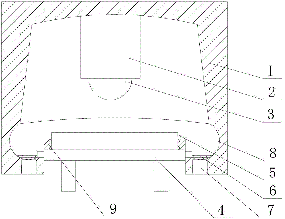
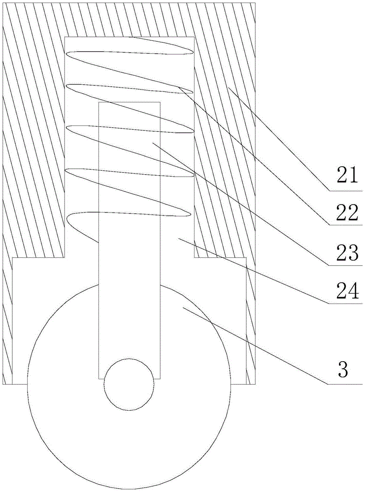
[0022] Such as figure 1 with figure 2 As shown, the present embodiment includes a circular workbench 4, on which a shield cover 1 is installed, the side of the shield cover 1 is provided with an opening for the workpiece 5 to enter and exit, and there is an opening in the shield cover 1 cavity, and an annular collecting tank 6 is arranged at the bottom of the cavity, and the side of the collecting tank 6 is connected to the side wall of the workbench 4, and the telescopic arm 2 moves through the top of the shielding cover 1 and is placed Directly above the workbench 4, a cutting wheel 3 is rotated at the end of the telescopic arm 2; it also includes a fan 7 installed at the bottom of the collection tank 6, the suction end of the fan 7 is connected to the collection tank 6, and A filter screen 8 is installed on the collection tank 6, there is a gap between the filter screen 8 and the bottom of the collection tank 6, and limit blocks 9 are installed at the two ends of the work...


PUM


Abstract

The invention discloses a chipping-blocking mechanism used for metal plate machining. The chipping-blocking mechanism comprises a working table; a shielding cover is installed on the working table, an opening is formed in the side edge of the shielding cover, and a cavity is formed in the shielding cover; a collecting groove is formed at the bottom of the cavity, the side edge of the collecting groove is connected with the side wall of the working table, and a cutting wheel is rotatably installed at the tail end of a telescopic arm; the suction end of a draught fan is connected with a collecting groove, a filter screen is installed on the collecting groove, and a space is reserved between the filter screen and the bottom of the collecting groove; and limiting blocks are installed at the two ends of the working table, sunken portions can be formed in the opposite side walls of the two limiting blocks in the direction away from the center of the working table, and rubber protrusions are installed in the middles of the sunken portions. During cutting, produced metal chippings star downwards sliding in a smooth mode along the inner wall of the cavity till dropping into the annular collecting groove, and after cutting is finished, the collecting groove can be cleared through simple instruments such as a broom; and meanwhile, the metal chippings accumulated in the collecting groove are centrally recovered to achieve secondary using.

Description

technical field [0001] The invention relates to a processing machine tool, in particular to a chip retaining mechanism for processing metal plate parts. Background technique [0002] When using a cutting machine to cut metal, a lot of metal debris will be splashed. These metal debris not only hurt the human body, but also easily enter the cutting machine, increase the wear of the cutting machine, and affect the service life of the cutting machine; Metal cutting machine tools that can both remove metal chips and collect metal chips for reuse appear. Contents of the invention [0003] The object of the present invention is to provide a chip retaining mechanism for metal plate processing, which facilitates the comprehensive collection of metal chips and realizes the purpose of repeated utilization. [0004] The object of the present invention is achieved through the following technical solutions: [0005] A chip-stopping mechanism for metal plate processing, comprising a ci...

Claims


Application Information

Patent Timeline
Patent Type & Authority Applications(China)
IPC IPC(8): B23Q11/08B23Q11/00
CPCB23Q11/08B23Q11/00B23Q11/0046B23Q11/0078
Inventor 许伟
Owner 重庆市木越机械制造有限公司
Why Eureka
Try Eureka