Automatic feeding and cutting device for metal plates

An automatic feeding and cutting device technology, which is applied in the direction of nibbling cutting devices, shearing devices, shearing machine accessories, etc., can solve the problem that the size and quality of the blanking cannot be guaranteed, and the efficiency of manual shearing and blanking can be solved. Low cost and large number of people required to achieve the effect of reducing labor costs and accident rates, fewer panel cutting personnel, and high production efficiency

Active Publication Date: 2017-06-09
CHANGSHU KAIBO STAINLESS EQUIP
View PDF8 Cites 7 Cited by
  • Summary
  • Abstract
  • Description
  • Claims
  • Application Information

AI Technical Summary

Problems solved by technology

This kind of cutting and blanking method not only requires a large number of people, is time-consuming and laborious, but also easily causes personal safety accidents. At the same time, the efficiency of manual cutting and blanking is low, the environment is poor, and the size and quality of the blanking cannot be guaranteed.

Method used


Image

  • Automatic feeding and cutting device for metal plates

Examples


Embodiment Construction

[0014] The applicant will describe in detail in the form of the following examples, but the description of the examples is not a limitation to the technical solution of the present invention, and any equivalent transformation made according to the concept of the present invention is only a formal rather than a substantive equivalent transformation All should be regarded as the scope of the technical solution of the present invention.

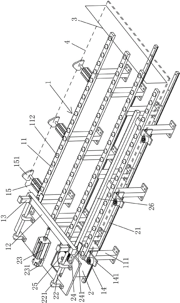
[0015] In the following descriptions, all concepts related to directionality or orientation of up, down, left, right, front and back are based on figure 1 The position shown is a reference, so it cannot be understood as a special limitation on the technical solution provided by the present invention.

[0016] see figure 1 , the present invention relates to an automatic feeding and cutting device for sheet metal, comprising a positioning device 1 and a power drag box 2, said positioning device 1 comprising a set of bed support bars 11 arranged s...


PUM


Abstract

The invention discloses an automatic feeding and cutting device for metal plates. The automatic feeding and cutting device comprises a positioning device and a power dragging box, wherein the positioning device comprises a group of lathe bed supporting rods, a longitudinal positioning clamping frame and a clamping air cylinder; a positioning lathe bed bracket is arranged below the lathe bed supporting rods; one side, in the width direction, of the lathe bed which consists of the lathe bed supporting rods, is equipped with a transverse positioning stop pin; the other side of the lathe bed is equipped with a transverse positioning clamping air cylinder; the longitudinal positioning clamping frame is arranged above one end of the lathe bed; a top plate of the transverse positioning clamping air cylinder is matched with the transverse positioning stop pin for realizing transverse positioning of plates; the clamping air cylinder is arranged on the longitudinal positioning clamping frame; the power dragging box is arranged on a pair of guide rails, and a guide rod is arranged above the guide rails; one end of the guide rod is connected with one side of the longitudinal positioning clamping frame, and the other end of the guide rod is arranged on a guide rod base; a longitudinal positioning clamping air cylinder and a pushing plate are further arranged above the power dragging box; and the pushing plate is matched with the clamping air cylinder to realize longitudinal positioning of plates. Plates are more accurate in shape and dimension while sheared; and the automatic feeding and cutting device is simple in structure, is safe to use, is convenient to operate, and is high in efficiency.

Description

technical field [0001] The invention belongs to the technical field of automatic cutting of metal plates, and in particular relates to an automatic feeding and cutting device for metal plates. Background technique [0002] In the manufacturing enterprises that use metal plates as raw materials, the precise cutting of plates is often the first process in the processing process. For the convenience and speed of follow-up processing, most of the purchased large flat plates with regular shapes such as rectangles are obtained through cutting. The desired shape and size, but because the plate is relatively thick, usually several tons to tens of tons, it is very difficult to manually cut it, and the efficiency is also very low. [0003] At present, the method of manually cutting large flat plates is that many people use hoisting equipment and hooks to hook the plates and move them to the prepared roller frame, and constantly adjust the distance to the required position, and then st...

Claims


Application Information

Patent Timeline
Patent Type & Authority Applications(China)
IPC IPC(8): B23D33/02B23D27/00
CPCB23D27/00B23D33/02
Inventor 钱惠东俞学军汪守成
Owner CHANGSHU KAIBO STAINLESS EQUIP
Why Eureka
Try Eureka