
Bridge pavement washing device

A technology for road cleaning and bridges, applied in road cleaning, cleaning methods, construction, etc., can solve the problems of large space occupation, easy knotting, inconvenient access, etc., to improve space utilization, reduce floor space, and improve work. The effect of efficiency

Active Publication Date: 2017-06-09
张家港和智珅知识产权有限公司
View PDF5 Cites 23 Cited by
  • Summary
  • Abstract
  • Description
  • Claims
  • Application Information

AI Technical Summary

Problems solved by technology

[0002] In the daily maintenance of the bridge, the cleaning of the bridge road surface is an important cleaning measure. In the existing ones, the cleaning vehicle is generally used for cleaning. However, the number of cleaning vehicles per day is limited and there are great limitations. After a sudden traffic accident on the bridge The cleaning is usually performed by maintenance personnel through an external water pipe. However, due to the long water pipe, it is inconvenient to take and place, which brings great difficulty to the cleaning work. It is very difficult to store, not only takes up a lot of space but also is easy to knot, which seriously affects the secondary use

Method used


Image

  • Bridge pavement washing device
  • Bridge pavement washing device
  • Bridge pavement washing device

Examples


Embodiment Construction

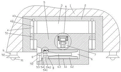
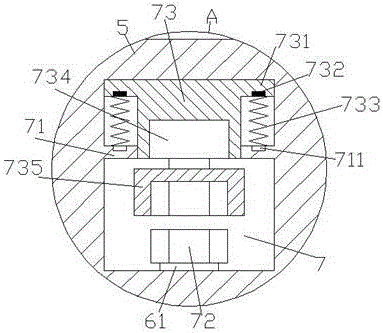
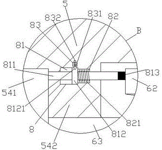
[0020] like Figure 1-Figure 6 As shown, a bridge pavement cleaning device of the present invention includes a wall 1 and a seat body 2 disposed in the wall 1, and lamp holders 9 are provided on the bottom surface of the wall 1 on the left and right sides of the seat body 2, The bottom of the lamp holder 9 is provided with an LED lighting lamp 92, and a lampshade 92 is arranged between the LED lighting lamp 91 and the lamp holder 9. The LED lighting lamp 91 is used for lighting when the device is used at night. The inner bottom of the seat body 2 is provided with a cavity 3, the cavity 3 is provided with a sliding piece 5, the outer wall on the left side of the sliding piece 5 is provided with a control area 52, and the sliding piece on the right side of the control area 52 5, the placement groove 54, the first empty chamber 6 is arranged in the sliding part 5 on the right side of the placement groove 54, and the first spacer 542 is arranged between the first empty chamber 6 a...


PUM


Abstract

The invention discloses a bridge pavement washing device. The bridge pavement washing device comprises a wall and a base body arranged in the wall, the bottom end faces, on the left side and the right side of the base body, of the wall are provided with lamp bases, the bottoms of the lamp bases are provided with LED floodlights, lampshades are arranged between the LED floodlights and the lamp bases, the bottom of the inside of the base body is provided with an accommodation cavity, the accommodation cavity is internally provided with a glide part, the outer wall of the left side of the glide part is internally provided with a manipulation area, the portion, at the right side of the manipulation area, of the glide part is internally provided with an accommodation groove, the portion, at the right side of the accommodation groove, of the glide part is internally provided with a first empty cabin, a first spacing block is arranged between the first empty cabin and the accommodation groove, the portion, above the first empty cabin, of the glide part is internally provided with a second empty cabin, the second empty cabin is internally provided with a first spacing block, the portion, above the first spacing block, of the second empty cabin is internally provided with a sliding platform, the tops of the two sides of the sliding platform are provided with flange blocks, the bottoms of the flange blocks are internally provided with magnets, the portions, opposite to the magnets, at the tops of the first spacing blocks are provided with electromagnetic coils, first tension springs are arranged between the electromagnetic coils and the magnets, and the bottom of the sliding platform penetrates through the first spacing blocks. The bridge pavement washing device is simple in structure and convenient to operate, can satisfy washing work at different distances, and can automatically achieve water pipe storage work; meanwhile, the bridge pavement washing device is small in occupied space and high in using stability, and thus the cleaning efficiency is improved.

Description

technical field [0001] The invention relates to the technical field of bridge facilities, in particular to a bridge road surface cleaning device. Background technique [0002] In the daily maintenance of the bridge, the cleaning of the bridge road surface is an important cleaning measure. In the existing ones, the cleaning vehicle is generally used for cleaning. However, the number of cleaning vehicles per day is limited and there are great limitations. After a sudden traffic accident on the bridge The cleaning is usually performed by maintenance personnel through an external water pipe. However, due to the long water pipe, it is inconvenient to take and place, which brings great difficulty to the cleaning work. There is great difficulty in storage, not only takes up a lot of space but also is very easy to tie, which seriously affects the secondary use. Contents of the invention [0003] The technical problem to be solved by the present invention is to provide a bridge ro...

Claims


Application Information

Patent Timeline
IPC IPC(8): E01H1/10
CPCE01H1/101
Inventor 钟潘霄
Owner 张家港和智珅知识产权有限公司
Learn More