
Building energy consumption monitoring and management system, method and device

A technology for energy consumption and buildings, applied in the general control system, control/regulation system, program control, etc., can solve the problem of long response time, inability to monitor and locate cash bills, and lack of remote telemetry, remote control, remote adjustment, and remote control. Letter, metering function and other issues

Active Publication Date: 2017-06-09
安徽德诺科技股份公司
View PDF7 Cites 14 Cited by
  • Summary
  • Abstract
  • Description
  • Claims
  • Application Information

AI Technical Summary

Problems solved by technology

[0003] Traditional hotel energy consumption monitoring needs to be divided into monitoring and control. Timers or light controllers are mainly used to enable energy-consuming equipment to be turned on or off at a specified time. Remote monitoring cannot be achieved, let alone real-time remote management.
Equipment inspection often uses manual inspection and customer complaints to check the operation status of energy-consuming equipment, which consumes a lot of manpower and material resources. When a failure occurs, personnel must be arranged for on-site repair and maintenance, and lacks intelligent control functions and response time long
[0004] On the other hand, the traditional monitoring and control system lacks the functions of remote telemetry, remote control, remote adjustment, remote signaling, and metering, and cannot locate and eliminate faults in a timely manner. It requires a lot of manpower and material resources, and cannot realize intelligent control. Real-time monitoring of consumption; at the same time, hotel room theft and cash running cannot be monitored and located

Method used


Image

  • Building energy consumption monitoring and management system, method and device
  • Building energy consumption monitoring and management system, method and device
  • Building energy consumption monitoring and management system, method and device

Examples


Embodiment Construction

[0092] In order to make the objects, technical solutions and advantages of the present invention more apparent, exemplary embodiments according to the present invention will be described in detail below with reference to the accompanying drawings. Apparently, the described embodiments are only some embodiments of the present invention, rather than all embodiments of the present invention, and it should be understood that the present invention is not limited by the exemplary embodiments described here. Based on the embodiments of the present invention described in the present invention, all other embodiments obtained by those skilled in the art without creative effort shall fall within the protection scope of the present invention.

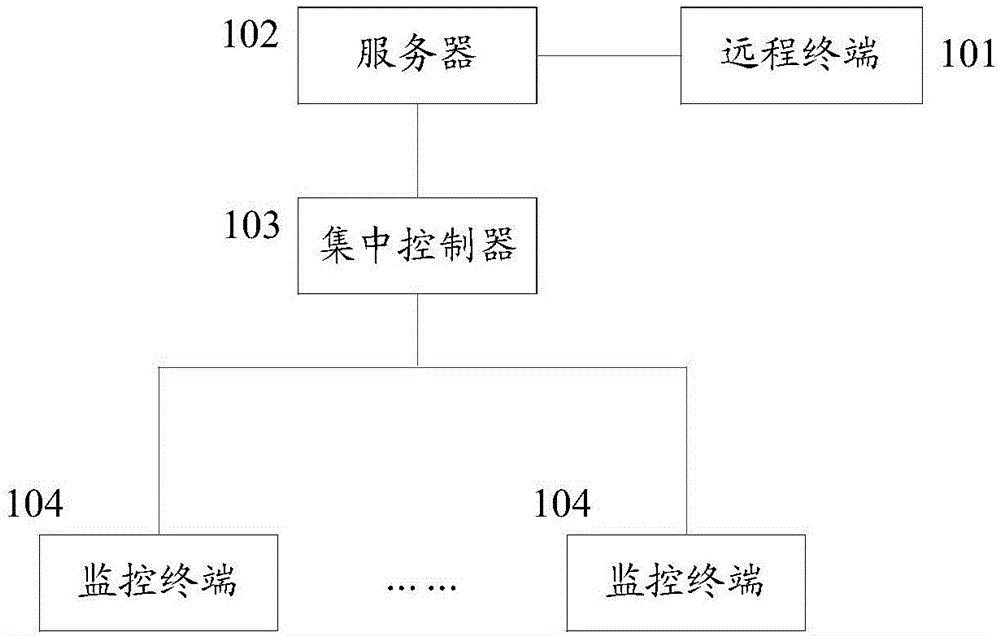
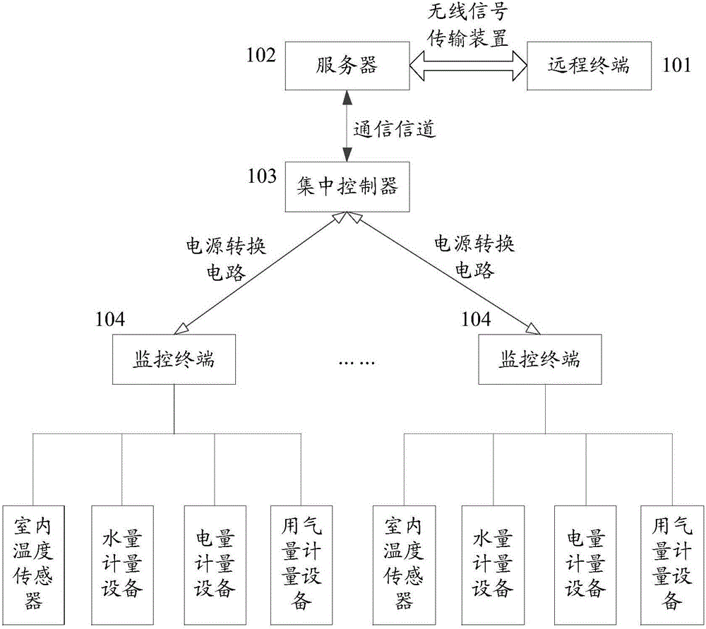
[0093] figure 1 It is a schematic block diagram of a system for monitoring and managing building energy consumption according to an embodiment of the present invention. figure 1 The system shown includes: a remote terminal 101 , a server 102 , a c...


PUM


Abstract

The invention provides a building energy consumption monitoring and management system comprising a remote terminal, a server, an integral controller and at least one monitoring terminal; the at least one monitoring terminal is used for monitoring state information and / or energy consumption information of the corresponding room, and sending the state information and / or energy consumption information to the integral controller; the server receives the state information and / or energy consumption information from the integral controller, parses the information so as to determine whether the corresponding room has energy consumption abnormity or not, and if yes, the abnormity condition is sent to the remote terminal; the remote terminal receives a user order on the abnormity conditions, and sends the order to the server. The system and method can detect and present the energy consumption information in real time, can detect energy consumption abnormity in real time, such as positioning fault equipment and determining room payment skipping conditions, thus timely and easily eliminating faults, ensuring the whole building energy consumption safety, and the maintenance is simple and fast.

Description

technical field [0001] The invention relates to the field of building energy consumption monitoring, in particular to a system, method and device for building energy consumption monitoring and management. Background technique [0002] At present, the energy consumption management of hotels is developing in the direction of intelligence. The remote monitoring and management system of hotel energy consumption is an indispensable means of energy consumption monitoring in hotel operation and management. An efficient energy consumption monitoring system is an inevitable requirement in hotel intelligent management. [0003] Traditional hotel energy consumption monitoring needs to be divided into monitoring and control. Timers or light controllers are mainly used to enable energy-consuming equipment to be turned on or off at a specified time. Remote monitoring cannot be achieved, let alone real-time remote management. Equipment inspection often uses manual inspection and customer ...

Claims


Application Information

Patent Timeline
Patent Type & Authority Applications(China)
IPC IPC(8): G05B19/048
CPCG05B19/048
Inventor 郜红兵
Owner 安徽德诺科技股份公司
Learn More