
Battery, terminal and battery protection method

A battery protection board, battery technology, applied in the field of electronics, can solve the problems of excessive temperature rise, battery overheating expansion, inability to detect battery changes, etc., to achieve the effect of avoiding excessive expansion

Inactive Publication Date: 2017-06-09
SHANGHAI YUDE COMM TECH
View PDF3 Cites 12 Cited by
  • Summary
  • Abstract
  • Description
  • Claims
  • Application Information

AI Technical Summary

Problems solved by technology

[0003] However, in the process of realizing the present invention, the inventor found that there are the following problems in the prior art: through the ordinary circuit to optimize the battery charging, although the battery can be quickly charged, but in the process of fast charging, the battery usually suffers from overheating and expansion The phenomenon
Although a thermistor is set on the battery protection board to detect temperature changes, such as figure 1 However, conventional protection circuit devices such as thermistors can only detect the rapid rise in temperature of the main board and battery protection board, but cannot detect changes in the battery itself, causing excessive expansion of the battery and causing serious damage to the performance of the battery. Great impact, and there will be a phenomenon of battery explosion due to excessive expansion, causing harm to users

Method used


Image

  • Battery, terminal and battery protection method
  • Battery, terminal and battery protection method
  • Battery, terminal and battery protection method

Examples


Embodiment Construction

[0025] In order to make the object, technical solution and advantages of the present invention clearer, various embodiments of the present invention will be described in detail below in conjunction with the accompanying drawings. However, those of ordinary skill in the art can understand that, in each implementation manner of the present invention, many technical details are provided for readers to better understand the present application. However, even without these technical details and various changes and modifications based on the following implementation modes, the technical solution claimed in this application can also be realized.

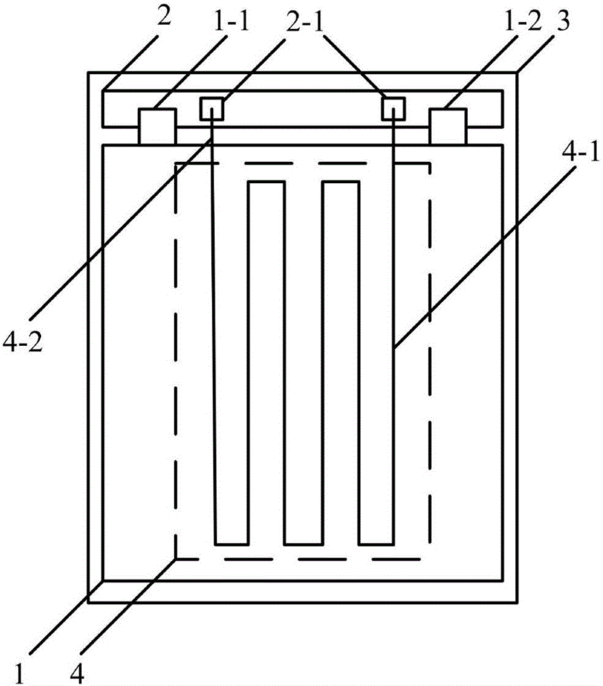
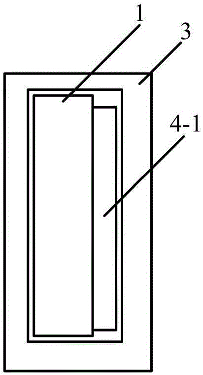
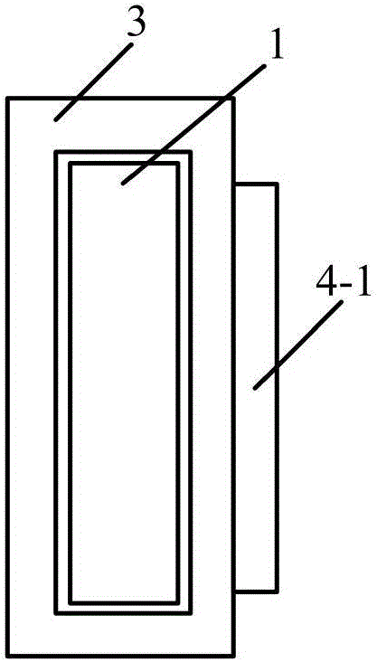
[0026] The first embodiment of the present invention relates to a battery such as figure 1 , 2 shown. The battery includes: a battery cell 1 , a battery protection plate 2 , a battery case 3 and a resistance strain sensor 4 . Wherein, the battery shell 3 covers the battery cell 1 and the battery protection plate 2, and the battery protec...


PUM


Abstract

The embodiment of the invention relates to the technical field of electronics, and discloses a battery, a terminal and a battery protection method. The battery comprises a battery core, a battery protection board, a battery shell and a resistance strain sensor. The battery shell covers the battery core and the battery protection board. The battery protection board is electrically connected with the positive electrode lug and the negative electrode lug of the battery core. The battery protection board is provided with a control chip. The resistance strain sensor comprises a sensitive grid and pins led out of the sensitive grid. The sensitive grid is fixed within the area of the battery core. The pins are electrically connected with the control chip on the battery protection board. According to the technical scheme of the invention, the sensitive grid is fixed with the area of the battery core, and the pins are electrically connected with the control chip on the battery protection board. In this way, during the charging process of the battery, the variation of the battery itself can be detected according to the variation of the resistance value. Therefore, the voltage and the current of the battery during the charging process can be reasonably controlled. The over-expansion of the battery is avoided.

Description

technical field [0001] The invention relates to the field of electronic technology, in particular to a battery, a terminal and a battery protection method. Background technique [0002] With the development of mobile terminals, mobile terminals such as mobile phones and tablet computers have become indispensable tools in life and work. As the function of the mobile terminal becomes more and more powerful, in order to ensure the standby time, the battery capacity of the mobile terminal is also increased, and the charging speed of the battery is also faster and faster. Mobile terminals currently on the market usually optimize battery charging through ordinary circuits, so as to realize fast charging of the battery. [0003] However, in the process of realizing the present invention, the inventor found that there are the following problems in the prior art: through the ordinary circuit to optimize the battery charging, although the battery can be quickly charged, but in the pr...

Claims


Application Information

Patent Timeline
IPC IPC(8): H02J7/00H01M10/48H01M10/44
CPCH01M10/44H01M10/48H02J7/0031H02J7/0036H02J7/008Y02E60/10
Inventor 王瑞斌
Owner SHANGHAI YUDE COMM TECH
Learn More