Welding tooling and welding method of motor vibrator

A technology of welding tooling and welding method, applied in the field of welding tooling of motor vibrators, can solve the problems of increasing cost and time, increasing the difficulty of positioning, complex structure, etc., and achieves the effect of easy positioning of the vibrator in the air, cost and time saving.

Active Publication Date: 2019-08-27
GOERTEK INC
View PDF6 Cites 0 Cited by
  • Summary
  • Abstract
  • Description
  • Claims
  • Application Information

AI Technical Summary

Problems solved by technology

In the process of use, it is found that it has the following disadvantages: the positioning in the Z-axis direction can easily block the laser welding equipment for welding the shrapnel structure, resulting in poor welding; and because the structure of the two-in-one speaker product is complex, it requires complex and cumbersome tooling , which further increases the difficulty of positioning, and also increases the cost and time; and once the existing welding tooling is finalized, it is difficult to adjust it, which is not convenient for product DOEs (Design of Experiments)

Method used


Image

  • Welding tooling and welding method of motor vibrator
  • Welding tooling and welding method of motor vibrator

Examples


Embodiment 1

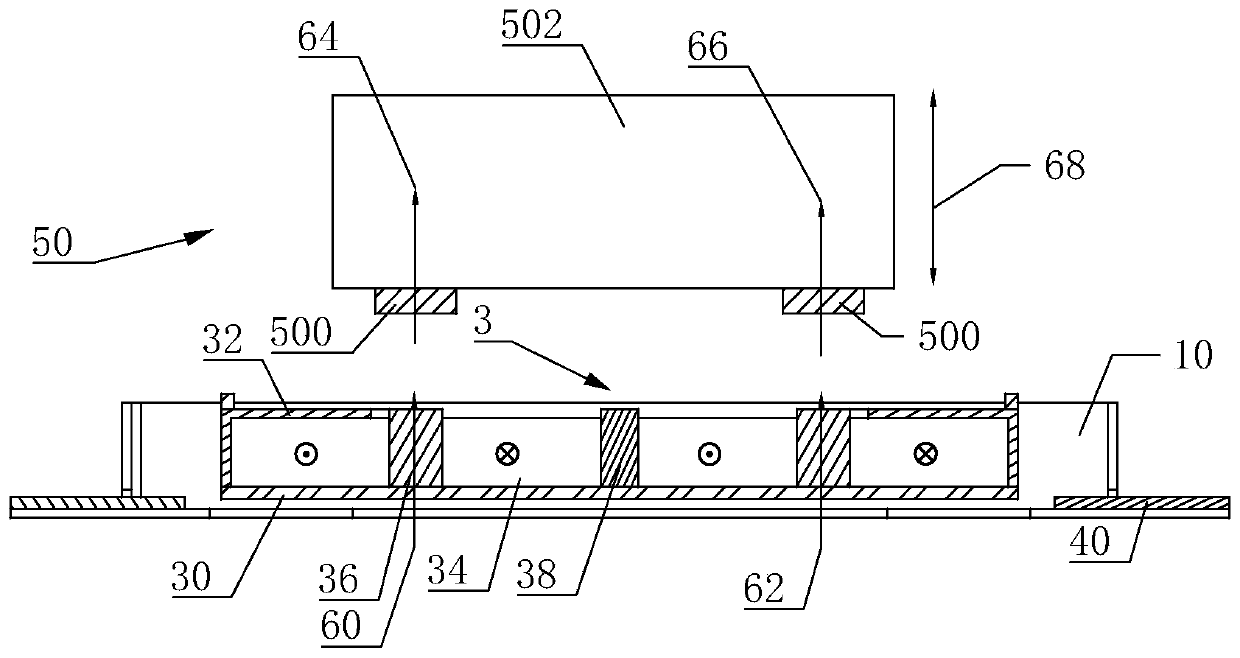
[0036] Such as figure 1 and figure 2 As shown, a welding tool for a motor vibrator includes a supporting component, the supporting component in this embodiment is preferably a mechanical arm 502 ; and a tooling magnet 500 installed at the lower end of the mechanical arm 502 . The number of tooling magnets 500 is at least two, and the two tooling magnets 500 located at the two ends of the mechanical arm 502 are respectively arranged corresponding to the two motor magnets located at the two ends of the motor vibrator 3; the motor magnets are electromagnets, and the tooling magnets The magnetization directions of the magnet 500 and the motor magnet are both vertical and the same.

[0037] The quantity of the tooling magnets 500 of the present invention is the same as that of the motor magnets, so that when welding, the tooling magnets 500 and the motor magnets attract each other one by one to attract the motor vibrator 3 .

[0038] The tooling magnet 500 used in this embodimen...

Embodiment 2

[0048] This embodiment is basically the same as Embodiment 1, the difference is:

[0049] Such as figure 1 and figure 2 As shown, in the welding tool 50 of this embodiment, the tool magnet 500 provided on the mechanical arm 502 is an electromagnet. That is, the fixture magnet 500 becomes an electromagnet after being fed with electric current.

[0050] A welding method for a motor vibrator, comprising the following steps:

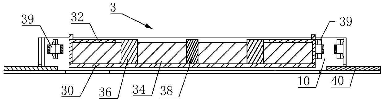
[0051] Step 1: Put the motor vibrator 3 on the motor housing 10, place the welding fixture 50 of the motor vibrator 3 on the top of the motor vibrator 3, and make the two fixture magnets 500 located at both ends of the mechanical arm 502 respectively correspond to the vibrator 3 The two motor magnets at both ends correspond to each other. The motor magnet in this embodiment includes a flat voice coil 34 and an armature 36 inserted in the middle of the voice coil; of course, the motor magnet is not limited to the structures listed in this embodiment.

...


PUM


Abstract

Disclosed is welding tooling of a motor vibrator, comprising a support member (502) and tooling magnets (500) mounted at a lower part of the support member (502), wherein the two blocks of tooling magnets (500), located at the lower part of the support member (502), are arranged correspondingly with two blocks of motor magnets located at two end parts of a motor vibrator (3) respectively; the motor magnets are electromagnets; and the magnetisation directions of the tooling magnets (500) and the motor magnets are the same, with both being vertical. Further disclosed is a welding method for a motor vibrator using the welding tooling. The space occupied by the welding tooling is small; and when welding, a laser welding apparatus is not obstructed, thereby increasing the accuracy of welding.

Description

technical field [0001] The invention relates to the technical field of electroacoustic products, in particular to a welding tool and a welding method for a motor vibrator. Background technique [0002] The two-in-one moving magnet speaker needs a shrapnel structure because it has a motor function. The shrapnel structure needs to use laser welding technology to weld it to the pot frame and shell of the vibrator. Since the bottom surface of the pot frame cannot be in direct contact with the shell, the vibrator needs to be suspended to a certain height for welding. [0003] The shrapnel structure welding tool in the prior art mainly locates the Z-axis height of the vibrator. In the process of use, it is found that it has the following disadvantages: the positioning in the Z-axis direction can easily block the laser welding equipment for welding the shrapnel structure, resulting in poor welding; and because the structure of the two-in-one speaker product is complex, it require...

Claims


Application Information

Patent Timeline
Patent Type & Authority Patents(China)
IPC IPC(8): H04R31/00
CPCH04R31/00
Inventor 汲鹏程许超
Owner GOERTEK INC
Why Eureka
Try Eureka