
Belt Drive Clamping Shoe Cover Machine

A technology of belt drive and shoe cover machine, which is applied in the direction of clothing, applications, hangers, etc., can solve the problems of inconsistent clamping force between the upper and lower sides, the appearance of the upper and lower parts, and the peeling off of the formed shoe film, and achieve the effect of fast melting speed and good welding quality

Active Publication Date: 2018-06-08
陈政
View PDF7 Cites 0 Cited by
  • Summary
  • Abstract
  • Description
  • Claims
  • Application Information

AI Technical Summary

Problems solved by technology

However, there are the following problems in the process of use: First, the motor drives the left and right splints to clamp the shoe film, and the upper and lower clamping forces are inconsistent, resulting in the upper clamping not being tight. The matching accuracy of the left and right splints is quite high.
Second, due to the inconsistency of the upper and lower clamping forces, the sealing end of the shoe film will not be welded firmly, and the sealing end of the shoe film will crack when walking, and the molded shoe film will fall off from the shoe, which will not work as a shoe cover.
For this reason, many manufacturers and people of insight have carried out development and research, but no satisfactory products have come out so far.

Method used


Image

  • Belt Drive Clamping Shoe Cover Machine
  • Belt Drive Clamping Shoe Cover Machine
  • Belt Drive Clamping Shoe Cover Machine

Examples


Embodiment Construction

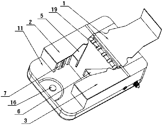
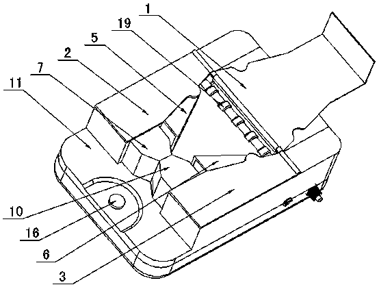
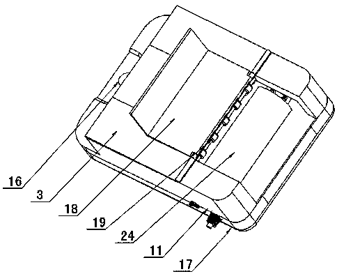
[0020] Figure 1 to Figure 5 Shown, for the present invention creates and adopts the concrete embodiment of the belt drive clamping shoe cover machine of electrothermal heating, it comprises base 17, middle cover 11, left and right movable plates 5,6, shoe film cylinder 24, shoe film conveying roller 19, Controller 23, shoe film clamping device, described shoe film clamping device comprises left and right clamping seats 7,10, clamping motor 13, double-ended screw rod 14, belt 15, and left and right clamping seats 7,10 are correspondingly arranged on On the left and right sliding seats 12 of the middle cover 11, the clamping motor 13 is fixed on the base 17, and the double-ended screw 14 is rotatably arranged on the base 17. The clamping motor 13 drives the double-ended screw 14 to rotate through the belt 15, and the left and right clamping Seats 7 and 10 are arranged on the double-ended screw rod 14 so as to be movable relative to each other through screw fit, and shoe film fu...


PUM


Abstract

The invention discloses a belt driving and clamping shoe cover machine. The belt driving and clamping shoe cover machine comprises a base (17), a middle cover (11), left and right movable plates (5 and 6), a shoe film roller (24), a shoe film conveying roller (19), a controller (23) and a shoe film clamping device, wherein the shoe film clamping device comprises left and right clamping seats (7 and 10), a clamping motor (13), a two-start worm (14) and a belt (15); the left and right clamping seats (7 and 10) are correspondingly arranged on a left and right slide seat (12) of the middle cover (11); the clamping motor (13) is fixed on the base (17); the two-start worm (14) is rotationally arranged on the base (17); the clamping motor (13) drives the two-start worm (14) to rotate through the belt (15); the left and right clamping seats (7 and 10) are correspondingly arranged on the two-start worm (14) in an oppositely movable manner through threaded matching; shoe film fusing devices are mounted on the left and right clamping seats (7 and 10) correspondingly. With adoption of the structure, the belt driving and clamping shoe cover machine has the advantages of being simple and reasonable in structure, convenient to operate and use, uniform in clamping force, firm in sealing and the like, and a formed shoe film is good in quality.

Description

technical field [0001] The invention relates to the technical field of household articles, in particular to a belt-driven shoe cover clamping machine for rapidly forming a shoe film on a shoe sole. Background technique [0002] With the rapid development of my country's economy, the living conditions of families have been significantly improved, and the requirements for indoor hygiene are getting higher and higher. In order to keep the room clean and hygienic, many families are equipped with a shoe cover machine at the door. The shoe cover machine does not need to take off shoes when guests come to the house. It will not cause cross-infection of athlete’s foot due to mutual wearing of slippers, and also avoids foot odor after taking off shoes. The phenomenon of smoked people is loved by the majority of users. For example, a shoe film cover machine disclosed in Chinese patent announcement number CN202698742U has a structural feature that the film on the foot groove will move...

Claims


Application Information

Patent Timeline
Patent Type & Authority Patents(China)
IPC IPC(8): A47G25/80
CPCA47G25/80
Inventor 陈政陈政果
Owner 陈政
Learn More