Novel electromechanical dust removal device

A dust removal device, electromechanical technology, applied in the direction of combination device, dispersed particle separation, chemical instruments and methods, etc., can solve the problems of low dust removal efficiency, structural adjustment, and endangering the personal health of on-site workers, so as to improve dust removal efficiency and dust removal effect, the effect of flexible structure adjustment

Inactive Publication Date: 2017-06-13
CHENGDU JUZHI IND DESIGN
View PDF7 Cites 16 Cited by
  • Summary
  • Abstract
  • Description
  • Claims
  • Application Information

AI Technical Summary

Problems solved by technology

[0002] During the production and processing of many products, a large amount of smoke or dust is often produced. These smoke or dust not only cause serious pollution to the environment of the work site, but also greatly endanger the personal health of the staff on site, so it is necessary to take measures Corresponding dust removal measures to absorb and remove dust generated at the work site
At present, there are corresponding electromechanical dust removal devices for dust removal operations, but due to structural and design restrictions, they cannot flexibly change positions and structure adjustments according to on-site dust removal requirements. At the same time, their dust removal efficiency is not high. Not ideal, these have greatly affected the performance of the dust removal device, and cannot meet the dust removal needs of the job site

Method used


Image

  • Novel electromechanical dust removal device

Examples


Embodiment Construction

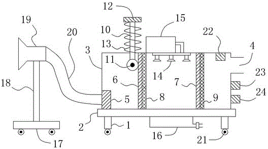
[0014] Such as figure 1 As shown, a new electromechanical dust removal device includes a bracket 1 and a base 2 located on the bracket 1. A box 3 is also provided on the base 2, and an air inlet is provided at the left bottom of the box 3. The top of the right side of the body 3 is provided with an air outlet 4, an exhaust fan 5 is provided at the air inlet, and a vertically arranged first partition 6 and a second partition are arranged in sequence from left to right in the box body 3. 7. A plurality of partition through holes (not shown in the figure) are uniformly distributed on the first partition 6 and the second partition 7 respectively, and on the right side of the first partition 6 and the second partition 7 The right side is also respectively provided with a first filter screen 8 and a second filter screen 9; a top wall through hole is also provided on the top wall of the casing 3, and a top wall through hole is also embedded in the top wall through hole to slide with ...


PUM


Abstract

The invention relates to a novel electromechanical dust removal device. The novel electromechanical dust removal device comprises a support, a base and a box body, wherein an air inlet and an exhaust fan are arranged at the bottom of the left side of the box body, an air outlet is formed in the top of the right side of the box body, a first separating plate and a second separating plate are arranged in the box body, separating plate through holes are formed in the first separating plate and the second separating plate, a first filter screen and a second filter screen are respectively arranged at the right sides of the first separating plate and the second separating plate, a top wall through hole is formed in the box body top wall, a first vertical bar is embedded and inserted in the top wall through hole, the bottom end of the first vertical bar is connected with a brush roller, a pressing disc is arranged at the top end of the first vertical bar, a spiral spring is arranged between the pressing disc and the box body top wall, a spraying head is arranged at the top end of the interior of the box body arranged between the first separating plate and the second separating plate, a water collecting tank is arranged below the spraying head, a movable seat is arranged at the left of the base, a second vertical bar is arranged on the movable seat, a dust removal cover is arranged on the second vertical bar, and the dust removal cover is connected with the air inlet by virtue of a ventilation hose. By adopting the structure, the novel electromechanical dust removal device provided by the invention has the advantages that flexible structural regulation can be carried out according to dust removal demand, and the dust removal efficiency and the effect are also improved.

Description

technical field [0001] The invention relates to a novel electromechanical dust removal device. Background technique [0002] During the production and processing of many products, a large amount of smoke or dust is often produced. These smoke or dust not only cause serious pollution to the environment of the work site, but also greatly endanger the personal health of the staff on site, so it is necessary to take measures Corresponding dust removal measures to absorb and remove the dust generated at the work site. At present, there are corresponding electromechanical dust removal devices for dust removal operations, but due to structural and design restrictions, they cannot flexibly change positions and structure adjustments according to on-site dust removal requirements. At the same time, their dust removal efficiency is not high. It is not ideal, and these have greatly affected the performance of the dust removal device, and cannot meet the dust removal needs of the work s...

Claims


Application Information

Patent Timeline
Patent Type & Authority Applications(China)
IPC IPC(8): B01D50/00
CPCB01D50/60
Inventor 文国栋
Owner CHENGDU JUZHI IND DESIGN
Why Eureka
Try Eureka