
Gas distribution device used for slurry bed reactor and slurry bed reactor

A gas distribution device and reactor technology, applied in chemical instruments and methods, chemical/physical processes, etc., can solve the problems of solid particle deposition, shutdown, poor gas uniform distribution effect, etc., and achieve the effect of solving deposition

Pending Publication Date: 2017-06-13
SHENWU TECH GRP CO LTD
View PDF0 Cites 1 Cited by
  • Summary
  • Abstract
  • Description
  • Claims
  • Application Information

AI Technical Summary

Problems solved by technology

Generally, the slurry bed reactor has disadvantages such as uneven gas distribution and solid particle deposition, which affect the effect of material reaction in the reactor body of the slurry bed reactor, and in serious cases, it will cause production failure and shutdown
[0003] Although some slurry bed reactors solve the problem of uniform gas distribution in the kettle body, they fail to solve the problem of solid particle deposition, and the pressure loss of the slurry bed reactor is relatively large, and the energy consumption is relatively high
Although other slurry bed reactors can solve the problem of solid particle deposition, the effect of gas uniform distribution is poor

Method used


Image

  • Gas distribution device used for slurry bed reactor and slurry bed reactor
  • Gas distribution device used for slurry bed reactor and slurry bed reactor
  • Gas distribution device used for slurry bed reactor and slurry bed reactor

Examples


Embodiment 1

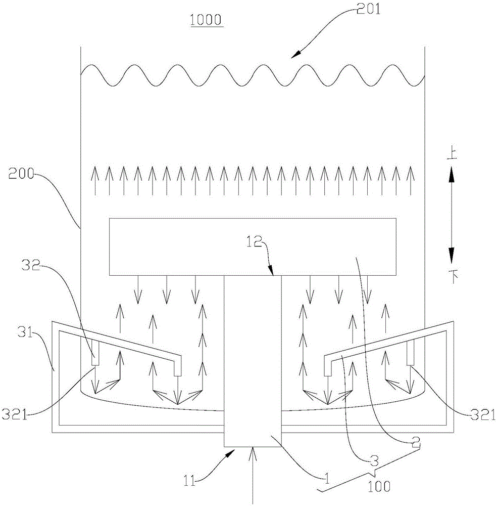
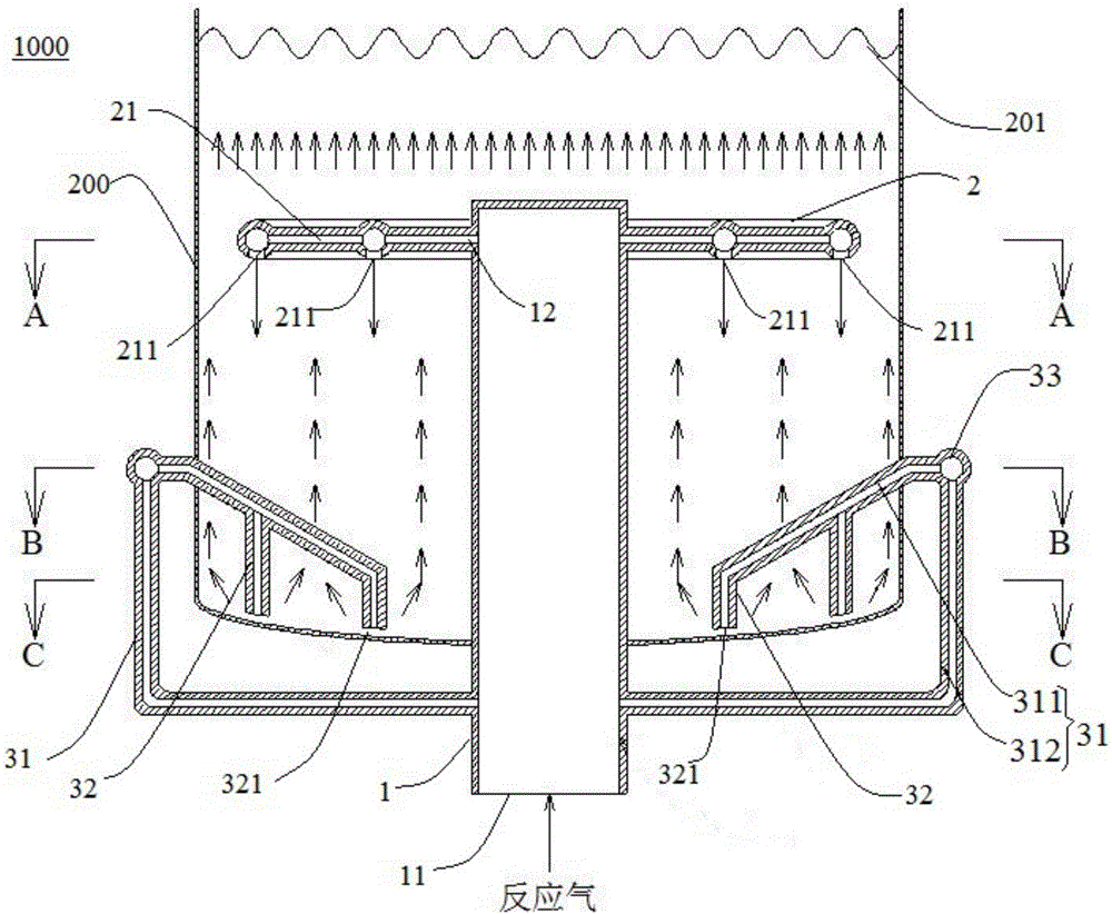
[0065] Such as Figure 2-Figure 5 As shown, the slurry bed reactor 1000 according to the embodiment of the present invention includes a kettle body 200 and a gas distribution device 100 . Wherein, the gas distribution device 100 is partly set in the kettle body 200 , the kettle body 200 contains the liquid-solid mixture, and the top wall of the kettle body 200 is provided with an exhaust port 201 . The kettle body 200 is formed in a cylindrical shape with an inner diameter of 500 mm. The slurry-bed reactor 1000 in this embodiment is a slurry-bed reactor 1000 for hydrogenating acetylene to produce ethylene.

[0066] The gas distribution device 100 includes an air inlet pipe 1 , a distribution member 2 and a spoiler 3 .

[0067] Specifically, the air inlet pipe 1 has an air inlet 11 and an air outlet 12. The air inlet pipe 1 extends into the kettle body 200 from the bottom wall of the kettle body 200 and is arranged coaxially with the kettle body 200. The air inlet 11 is locat...

Embodiment 2

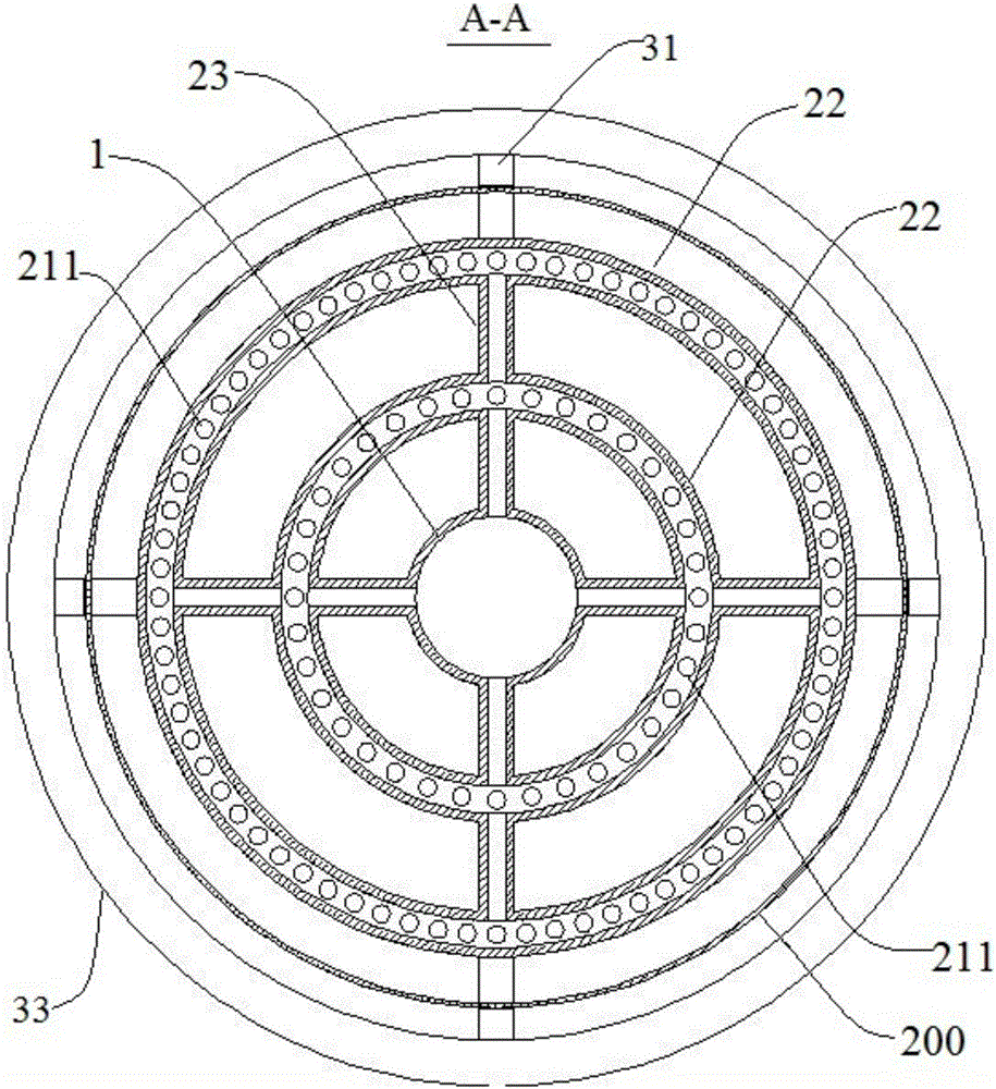
[0074] Such as Figure 6-Figure 7 As shown, the slurry bed reactor 1000 according to the embodiment of the present invention includes a kettle body 200 and a gas distribution device 100 . Wherein, the gas distribution device 100 is partly set in the kettle body 200 , the kettle body 200 contains the liquid-solid mixture, and the top wall of the kettle body 200 is provided with an exhaust port 201 . The kettle body 200 is formed in a cylindrical shape with an inner diameter of 500 mm. The slurry-bed reactor 1000 in this embodiment is a slurry-bed reactor 1000 for hydrogenating acetylene to produce ethylene.

[0075] The gas distribution device 100 includes an air inlet pipe 1 , a distribution member 2 and a spoiler 3 .

[0076] Specifically, the air inlet pipe 1 has an air inlet 11 and an air outlet 12. The air inlet pipe 1 extends into the kettle body 200 from the bottom wall of the kettle body 200 and is arranged coaxially with the kettle body 200. The air inlet 11 is locat...


PUM


Abstract

The invention discloses a gas distribution device for a slurry bed reactor and the slurry bed reactor. The gas distribution device includes: an air inlet pipe, the air inlet pipe has an air inlet and an air outlet; a uniform distribution piece, the uniform distribution piece is arranged on the air intake pipe, and a gas passage is arranged in the uniform distribution piece, the gas passage communicates with the air outlet, and the gas passage The bottom wall is provided with a plurality of uniform air holes, and the plurality of uniform air holes are distributed around the circumference of the inlet pipe at intervals; the spoiler, the spoiler includes a plurality of air injection pipes located in the kettle body, and each air injection pipe has an air injection pipe with an opening facing downward. Mouth, each air injection port is positioned at the below of the uniform air hole, and each air injection pipe communicates with the part outside the kettle body of the air inlet pipe through the connecting pipeline extending out of the still body. According to the gas distribution device of the present invention, the uniform distribution of the gas in the still body can be realized under relatively low pressure drop, and the problem of the deposition of solid particles in the still body can be effectively solved.

Description

technical field [0001] The invention relates to the technical field of slurry bed reactors, in particular to a gas distribution device for the slurry bed reactor and the slurry bed reactor. Background technique [0002] The slurry bed reactor is an important gas-liquid-solid multiphase reaction device, especially suitable for heterogeneous catalytic reactions such as acetylene hydrogenation to ethylene and Fischer-Tropsch synthesis. Generally, the slurry bed reactor has disadvantages such as uneven gas distribution and solid particle deposition, which affect the effect of material reaction in the reactor body of the slurry bed reactor, and in severe cases, it will cause production failure and shutdown. [0003] Although some slurry bed reactors solve the problem of uniform gas distribution in the kettle, they fail to solve the problem of solid particle deposition, and the slurry bed reactor has a large pressure loss and high energy consumption. Although other slurry bed rea...

Claims


Application Information

Patent Timeline
Patent Type & Authority Applications(China)
IPC IPC(8): B01J8/22
CPCB01J8/22B01J8/1818B01J8/1872B01J2208/00938
Inventor 刘周恩史雪君余海鹏苏二强李少雨吴黎阳黄伟史东军吴道洪
Owner SHENWU TECH GRP CO LTD
Learn More