Turnover mechanism for assembling of large parts

A technology of component assembly and turning mechanism, which is applied in metal processing, workbench, metal processing equipment, etc., can solve the problems that the force layout is not considered, the setting of the center of gravity is not optimized, and the working time is shortened, so as to shorten the working time and reduce the The number of workers and the effect of smooth rotation

Active Publication Date: 2017-06-13
SHANGHAI JIAO TONG UNIV
View PDF6 Cites 4 Cited by
  • Summary
  • Abstract
  • Description
  • Claims
  • Application Information

AI Technical Summary

Problems solved by technology

[0004] Aiming at the shortcomings of the prior art that the setting of the center of gravity is not optimized enough to easily cause components to overturn, and the force layout does not take into account the characteristics of large components, it is easy to cause damage. It can be turned from the vertical state to the horizontal state without lifting the truss truck. While simplifying the turning process, it can reduce the number of workers, shorten the working time and improve the efficiency.

Method used


Image

  • Turnover mechanism for assembling of large parts
  • Turnover mechanism for assembling of large parts
  • Turnover mechanism for assembling of large parts

Examples


Embodiment 1

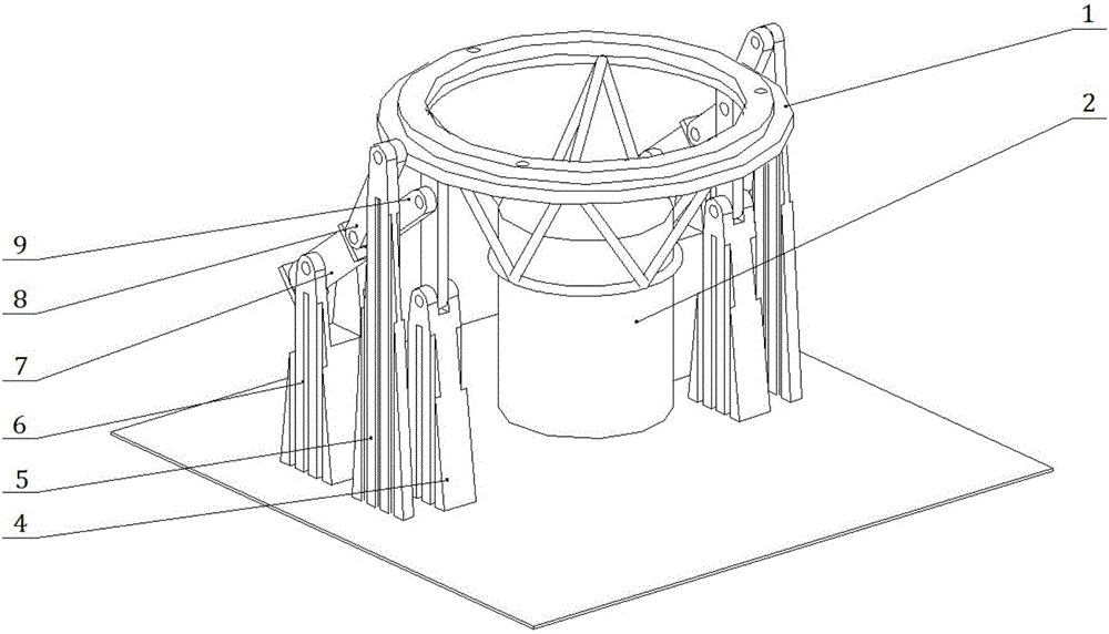
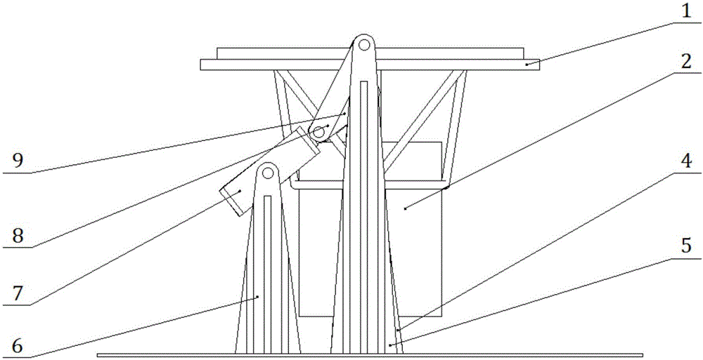
[0018] Such as figure 1 with figure 2 As shown, this embodiment includes: a turning bracket 1, a pneumatic device 7, a fixing support 4 of the turning bracket, a connecting rod fixing support 5 and a fixing support 6 of the pneumatic device, wherein: the large part 2 is fixed on the turning bracket 1 Above, the left and right sides of the flipping bracket 1 are respectively symmetrically provided with a flipping bracket fixed support 4, a connecting rod fixed support 5 and a pneumatic device fixed support 6. One end of the pneumatic device 7 is rotationally connected with the pneumatic device fixed support 6, and the other One end is respectively connected to the first connecting rod 8 and the second connecting rod 9 in rotation, the first connecting rod 8 is connected to the connecting rod fixed support 5 in rotation, the second connecting rod 9 is connected to the turning bracket 1 in rotation, and the turning bracket 1 is connected to the turning bracket 1. The fixed supp...


PUM


Abstract

The invention belongs to the technical field of automatic assembling of large parts, and provides a turnover mechanism for assembling of the large parts. The turnover mechanism comprises a turnover bracket, pneumatic devices, turnover bracket fixing supporting bases, connecting rod fixing supporting bases and pneumatic device fixing supporting bases. The turnover bracket fixing supporting bases, the connecting rod fixing supporting bases and the pneumatic device fixing supporting bases are symmetrically arranged on the left side and the right side of the turnover bracket. One end of each pneumatic device is connected with the corresponding pneumatic device fixing supporting base in a rotating mode, and the other end of each pneumatic device is connected with the corresponding first connecting rod and the corresponding second connecting rod in a rotating mode. The first connecting rods are connected with the connecting rod fixing supporting bases in a rotating mode, and the second connecting rods are connected with the turnover bracket in a rotating mode. The turnover bracket is connected with the turnover bracket fixing supporting bases in a rotating mode. By the adoption of the turnover mechanism for assembling of the large parts, the purpose that the large parts can be overturned from the vertical state to the horizontal state in the turnover process on the premise that the large parts do not need to be hoisted by a travelling crane can be achieved, the turnover process is simplified, the number of workers is reduced, the working time is shortened, and the efficiency is improved.

Description

technical field [0001] The invention relates to a technology in the field of automatic assembly of large parts, in particular to a turning mechanism for assembling large parts. Background technique [0002] The automated assembly of large components refers to the use of mechanized and automated equipment to perform assembly tasks for large components on an assembly line or in an assembly unit. It has the advantages of high precision and short time consumption. [0003] At present, the overturning of large parts all adopts the mode of lifting and overturning. In the process of hoisting and overturning, it is first necessary to use a jack to lift the component to a certain height, then install the overturning sling on the large component and connect the sling to the truss, and then use the truss to lift the large component and realize Flip. During this process, overturning involves more than ten kinds of auxiliary equipment such as spreaders, hanging beams, lifting lugs, an...

Claims


Application Information

Patent Timeline
Patent Type & Authority Applications(China)
IPC IPC(8): B23P19/00B25H1/10
CPCB23P19/00B25H1/10
Inventor 王皓张壮陈根良赵勇孔令雨余海东
Owner SHANGHAI JIAO TONG UNIV
Why Eureka
Try Eureka