Composite material connecting joint

A technology for connecting joints and composite materials, which is applied in aircraft parts, aircraft control, transportation and packaging, etc. It can solve the problems of galvanic corrosion stress, fatigue life, and increase the weight of counterweights, so as to reduce the weight of counterweights, improve reliability, Guarantee the effect of appearance

Inactive Publication Date: 2017-06-13
R&D INST OF CHINA AVIATION IND GENERAL AIRCRAFT
View PDF4 Cites 2 Cited by
  • Summary
  • Abstract
  • Description
  • Claims
  • Application Information

AI Technical Summary

Problems solved by technology

[0002] Generally, the rudder surface of an aircraft adopts a composite material structure, and the rudder surface connection joints often use metal joints. The metal joints and the composite material rudder surface have galvanic corrosion problems and stress caused by thermal expansion, which affects structural fatigue and life.
Moreover, the metal joints generally adopt the connection method of concentrated force. The rudder surface must have corresponding beams and ribs to strengthen the structure. The shape of the leading edge skin must be modified or notched for the connection of metal parts, which affects the aerodynamic performance of the leading edge of the rudder.
Moreover, the metal joint has a certain height, and the joint is located behind the centerline of the rotating shaft, so more counterweight must be added to the front section of the rotating shaft

Method used


Image

  • Composite material connecting joint
  • Composite material connecting joint
  • Composite material connecting joint

Examples


Embodiment Construction

[0009] The specific implementation manner of the patent of the present invention will be further described below in conjunction with the accompanying drawings. Based on the implementation manners in the present invention, all other implementations obtained by persons of ordinary skill in the art without making creative efforts belong to the protection scope of the present invention.

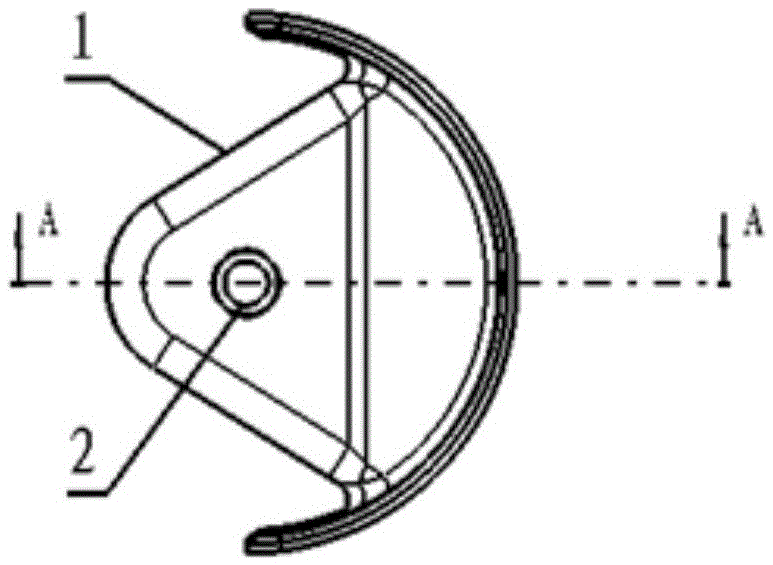
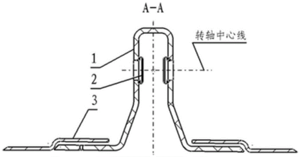
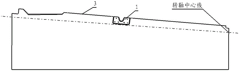
[0010] Please refer to Figure 1 to Figure 3 As shown in Fig. 3, a composite material joint opening is made on 3, 2 and 1 are glued together to form a whole, and then the glued assembly of 1 and 2 is connected to 3 through the nut of the bracket.


PUM


Abstract

The invention belongs to the field of airplane structure design and relates to the improvement in an airplane control plane connecting joint which is a detachable composite material double-lug joint with linings. The joint is characterized in that the joint comprises a detachable composite material control plane connecting joint body 1, the two ends of the joint body are connected with the metal linings 2 in a glued manner, a control plane skin 3 is recessed downwards, a notch is formed in the control plane skin 3, and the control plane connecting joint body 1 is connected with the control plane skin 3 through supporting plate nuts. The composite material connecting joint replaces a metal connecting joint, the appearance of the front edge of a control plane is well guaranteed, the joint is located on the front face of the center of a rotary shaft due to the n-shaped joint recessed inwards, and the balance weight of the control plane is reduced.

Description

technical field [0001] The patent of the invention is a composite material connecting joint Background technique [0002] Generally, the rudder surface of an aircraft adopts a composite material structure, and the rudder surface connection joints often use metal joints. The metal joints and the composite material rudder surface have galvanic corrosion problems and stress caused by thermal expansion, which affects structural fatigue and life. Moreover, metal joints generally adopt the connection method of concentrated force. The rudder surface must have corresponding beams and ribs to strengthen the structure. The shape of the leading edge skin must be modified or notched for the connection of metal parts, which affects the aerodynamic performance of the leading edge of the rudder. Moreover, the metal joint has a certain height, and the joint is located behind the centerline of the rotating shaft, so more counterweight must be added to the front section of the rotating shaft....

Claims


Application Information

Patent Timeline
Patent Type & Authority Applications(China)
IPC IPC(8): B64C5/00
CPCB64C5/00
Inventor 曾小苗梁旺盛杨鉴威
Owner R&D INST OF CHINA AVIATION IND GENERAL AIRCRAFT
Why Eureka
Try Eureka