Light Electric Slewing Hook Set

A hook group, electric technology, applied in the direction of load hanging components, load blocks, transportation and packaging, etc., can solve the problems of difficult parts processing, large volume and weight, complex structure, etc., to achieve stable combination, safe and reliable work , the effect of simple mechanism structure

Active Publication Date: 2016-03-16
DALIAN HUARUI HEAVY IND CRANE CO LTD +1
View PDF6 Cites 0 Cited by
  • Summary
  • Abstract
  • Description
  • Claims
  • Application Information

AI Technical Summary

Problems solved by technology

The disadvantages of the electric rotary hook group in the prior art are: complex structure, large volume and weight, difficult parts processing, and high cost

Method used


Image

  • Light Electric Slewing Hook Set
  • Light Electric Slewing Hook Set
  • Light Electric Slewing Hook Set

Examples


Embodiment Construction

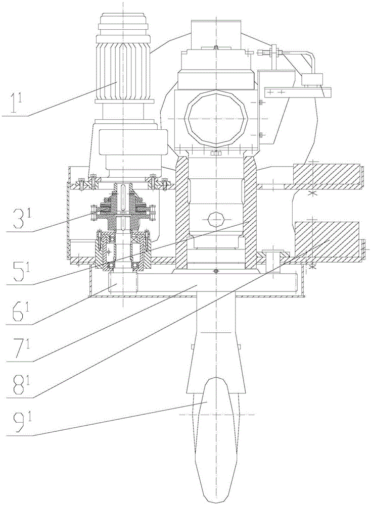
[0052] The present invention will be further described below in conjunction with drawings and embodiments.

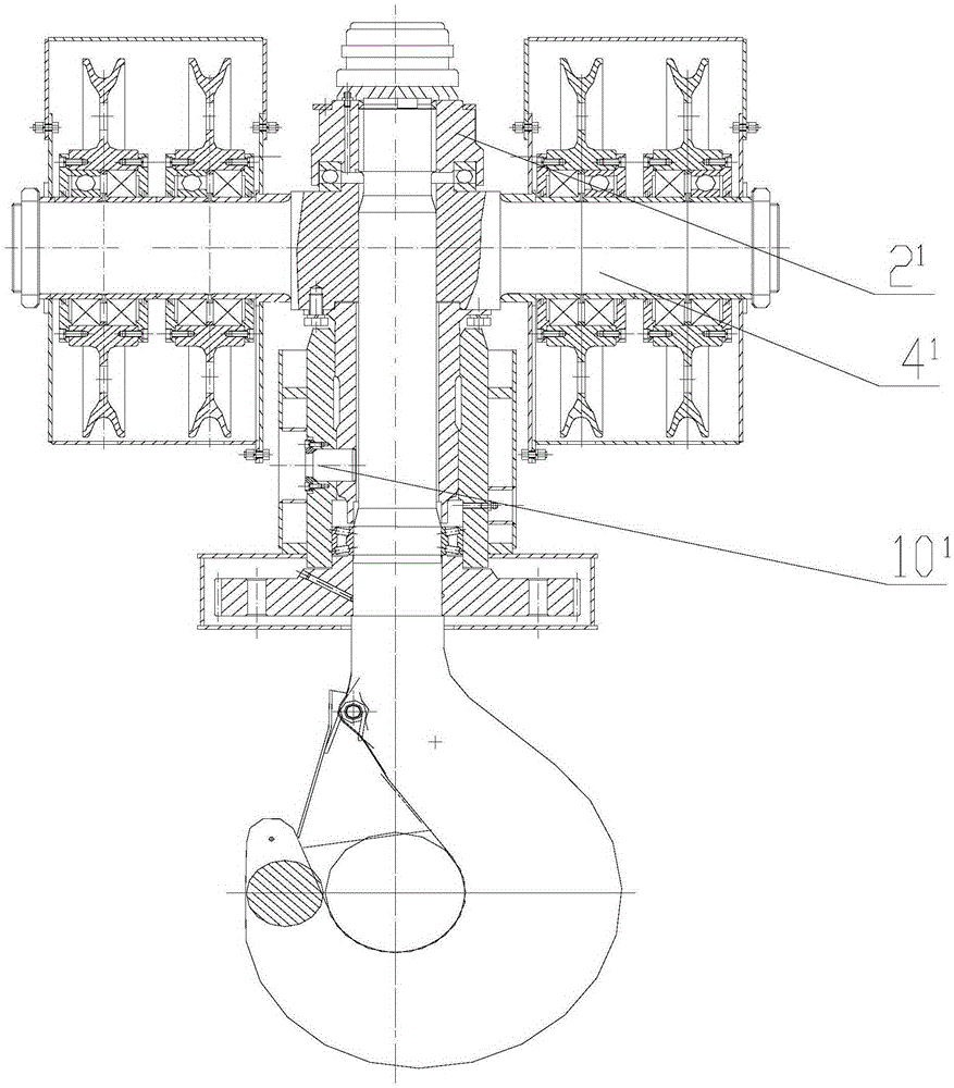
[0053] The light-duty electric slewing hook set includes a deceleration motor, a pulley mechanism, a gear mechanism and a hook mechanism. The deceleration motor 1 has a side flange and an end flange; the pulley mechanism includes a pulley shaft 2 and a pulley, and the two sets of pulleys are installed on the The two ends of the pulley shaft 2; the gear mechanism includes a pinion 13, a support 12 and a gear assembly 9, and the pinion 13 is fixed on the output shaft of the reduction motor 1 by a key 15; the support 12 is a conical frame, and the top surface of the support 12 is a large Ring, the small ring on the bottom surface is the bearing seat, the top surface of the support 12 is bolted to the flange of the reduction motor 1 end, the bearing 16 is installed in the bearing seat on the bottom surface of the support 12, the pinion 13 is supported on the bearing 16, and ...


PUM


Abstract

A light electric rotating lifting hook group comprises a gear motor, a pulley mechanism, a gear mechanism and a lifting hook mechanism, wherein the pulley mechanism comprises two groups of pulleys mounted at two ends of a pulley shaft; a pinion of the gear mechanism is fixedly connected onto the gear motor; a gear assembly integrates a friction block, an inner ring, bolt groups and a butterfly spring through press plates and is fixedly connected with a lifting hook handle through interference fit; according to the lifting hook mechanism, the upper end of the lifting hook handle sequentially penetrates through an adjusting sleeve on the upper surface of the gear assembly, a guide bearing, a support, a lifting hook beam and a thrust bearing to be bolted with a lifting hook nut, and shaft holes in two ends of each of two yoke plates are suspended on the lifting hook beam and the pulley shaft in a sleeving manner respectively; a lateral flange of the gear motor is bolted on the lifting hook beam and the support; and the pinion is meshed with a gear ring of the gear assembly. The light electric rotating lifting hook group has the benefits of simple and novel structure, convenience in manufacturing, low cost, convenience in binding force adjustment, small number of transmission chains, high efficiency, small mechanism sizes, light counterweight, high work precision and safe and reliable operation.

Description

technical field [0001] The invention relates to the field of hoisting and transportation, and relates to hoisting equipment, in particular to an electric rotary hook set. Background technique [0002] The electric rotary hook group of prior art is as Figure 1 to Figure 5 shown. Its main component is a flange-mounted geared motor (1 1 ), hook nuts (2 1 ), friction safety clutch (3 1 ), T-shaft (4 1 ), T-beam (5 1 ), gear shaft (6 1 ), gear (7 1 ), counterweight (8 1 ) and hooks (9 1 ) and other components. One end of the T-beam supports components such as geared motor, friction safety coupling and gear shaft, and the other end is balanced by a counterweight. The T-beam uses a pin shaft (10 1 ) hanging on the T-shaft (4 1 ) on the vertical axis side. image 3 is the front view of the T-axis, the T-axis consists of the horizontal axis (4 1 -1) and the vertical axis (4 1 -3) with bolts (4 1 -2) Bolted, horizontal shaft (4 1 -1) for hanging the pulley block; Fi...

Claims


Application Information

Patent Timeline
Patent Type & Authority Patents(China)
IPC IPC(8): B66C11/00
CPCB66C1/34
Inventor 丁志强
Owner DALIAN HUARUI HEAVY IND CRANE CO LTD
Why Eureka
Try Eureka