Tree pruning elevator

A technology of tree pruning and elevators, applied in the direction of lifting frames, lifting devices, etc., can solve problems such as time-consuming, labor-intensive, and potential safety hazards, and achieve the effects of improving work efficiency, safe and reliable use, and reducing workload

Active Publication Date: 2019-05-21
STATE GRID SHANDONG ELECTRIC POWER +2
View PDF9 Cites 0 Cited by
  • Summary
  • Abstract
  • Description
  • Claims
  • Application Information

AI Technical Summary

Problems solved by technology

[0003] The purpose of the present invention is to provide a special elevator for tree pruning to overcome the defects of potential safety hazards and time-consuming and labor-intensive problems in the prior art when pruning trees under cable lines

Method used


Image

  • Tree pruning elevator
  • Tree pruning elevator
  • Tree pruning elevator

Examples


Embodiment 1

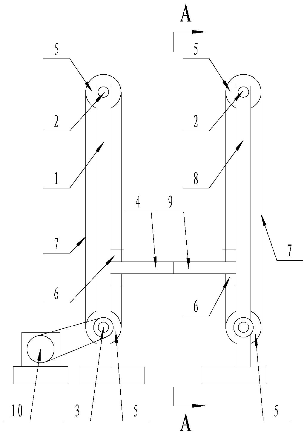
[0021] Such as figure 1 , figure 2 Shown, a kind of lift special for tree pruning, comprises the first lifting frame 1, the second lifting frame 8, the first lifting frame 1 and the second lifting frame 8 are respectively provided with lifting transmission mechanism, the first lifting frame 1 and the second lifting frame The lifting transmission mechanisms of the two lifting frames 8 are respectively connected with the first lifting platform 4 and the second lifting platform 9, and the first lifting platform 4 and the second lifting platform 9 are detachably connected. The first lifting frame 1 and the second lifting frame 8 can be used alone or in combination. It is flexible and convenient to use alone, and is suitable for single-person work. The combined use has a wide range of work, is safer and more reliable, and is suitable for multi-person work.

Embodiment 2

[0023] The lifting transmission mechanism includes a motor 10, a transmission shaft 3 and a driven shaft 2, and the transmission shaft 3 and the driven shaft 2 are respectively fixed with at least one group of sprockets 5, and the chain wheels 5 of the transmission shaft 3 and the driven shaft 2 The sprocket 5 is arranged vertically correspondingly and is connected by a chain 7 , and one end of the transmission rotating shaft 3 is also provided with a sprocket 5 connected to the motor 10 by the chain 7 . The structure of the lifting transmission mechanism is not limited to the above-mentioned structure, and other structures similar to the present application can also be used, such as gear transmission, hydraulic lifting and other structures.

[0024] Other structures of this embodiment are the same as those of Embodiment 1.

Embodiment 3

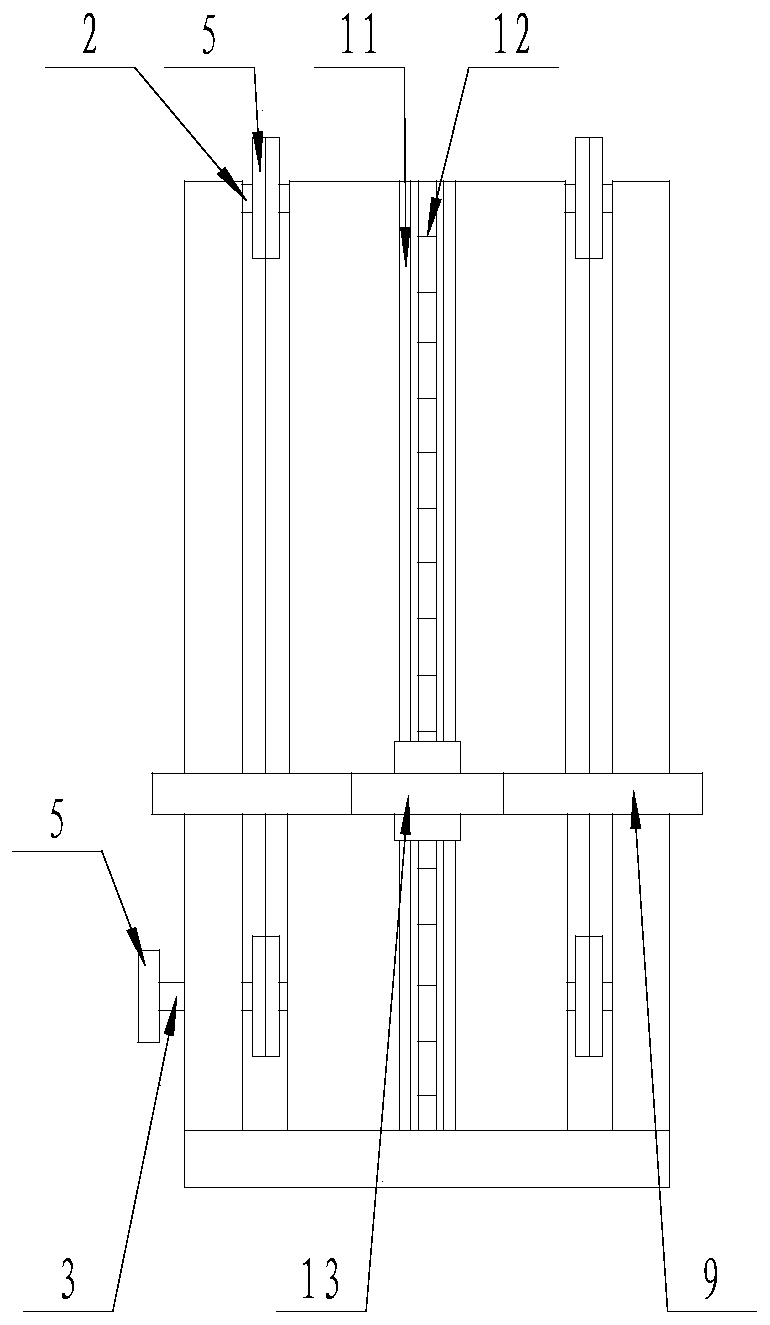
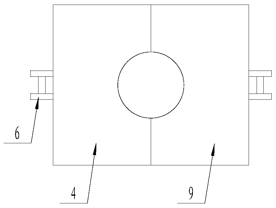
[0026] Such as Figure 1-4 As shown, an anti-falling device is also provided between the lifting platform and the lifting frame. The anti-falling device includes a hook 12, a slide rail 11 and a hanging seat 6, and the hooks 12 are vertically arranged and fixed on the first lifting frame 1 and the second lifting frame 8. Inside, the slide rail 11 is arranged in parallel on both sides of the hook 12, one end of the hanging base 6 is movably connected with the slide rail 11, and the other end is fixedly connected with the first lifting platform 4 or the second lifting platform 9, and the front connecting plate of the hanging base 6 is provided with The arc-shaped hole track 14 is high and low, and a load-bearing pin 15 that can slide along the arc-shaped hole track 14 is arranged inside the arc-shaped hole track 14 .

[0027] Such as Figure 4 As shown, during the slow lifting process of the lifting platform, after the load-bearing pin 15 touches the hook 12, it slowly rises al...


PUM


Abstract

The invention discloses a lifting ladder special for tree clipping and belongs to the field of electric power ascending tools. The lifting ladder comprises a first lifting frame and a second lifting frame. The first lifting frame and the second lifting frame are each provided with a lifting transmission mechanism. The lifting transmission mechanism of the first lifting frame is connected with a first lifting platform, and the lifting transmission mechanism of the second lifting frame is connected with a second lifting platform. The first lifting platform is connected with the second lifting platform in a separable manner. The lifting ladder is mainly used for clipping trees under wires, the safety performance is greatly enhanced, the workload of workers is reduced, and the working efficiency of tree clipping is improved.

Description

technical field [0001] The invention belongs to a climbing tool, in particular to a special lift for tree pruning. Background technique [0002] The growth of offline trees has a certain impact on the erection of electric wires and the safe operation of lines, so the branches of trees need to be trimmed regularly. At present, when trimming large-scale green trees under the line, the staff are using ordinary ladders, pruning with one hand and holding the ladder with the other hand, and it is very time-consuming and laborious to trim, and there is a danger of falling off the ladder if you are not careful. It is easy to produce some unsafe factors. Moreover, ordinary ladders have limited activity space. For trees with larger branches, the staff can only trim the nearby branches when standing on the ladder. Therefore, it is necessary to constantly change the position of the ladder to trim the entire tree. The staff needs to carry tools constantly Going up and down the ladder i...

Claims


Application Information

Patent Timeline
Patent Type & Authority Patents(China)
IPC IPC(8): B66F7/02B66F7/28
CPCB66F7/02B66F7/28
Inventor 王廷平郑元伟陈星延高成成林建姜楠孙京锋李中凯庞亚亚刘洋葛路东胡忠彩刘豪
Owner STATE GRID SHANDONG ELECTRIC POWER
Why Eureka
Try Eureka