Guardrail structure and guardrail lamp

A guardrail structure and guardrail light technology, applied in the directions of roads, lighting applications, traffic signals, etc., can solve the problems of not considering lamp protection, low impact energy, small protection area, etc., and achieve easy assembly and maintenance, reduce impact, and avoid glare. purpose effect

Pending Publication Date: 2017-06-13
SHANGHAI SANSI ELECTRONICS ENG +2
View PDF14 Cites 3 Cited by
  • Summary
  • Abstract
  • Description
  • Claims
  • Application Information

AI Technical Summary

Problems solved by technology

[0005] The guardrail body of the lighting guardrail provided by the prior art is in the shape of a round tube or an ellipse tube, and its protective area is small, and once it collides with a vehicle, the impact energy it can absorb is small, thereby making it poor in crashworthiness. In addition, the existing The buffer structure of the guardrail in the technology only considers its own impact resistance, but does not take into account the protection of the installation part of the lamp

Method used


Image

  • Guardrail structure and guardrail lamp
  • Guardrail structure and guardrail lamp
  • Guardrail structure and guardrail lamp

Examples


no. 1 example

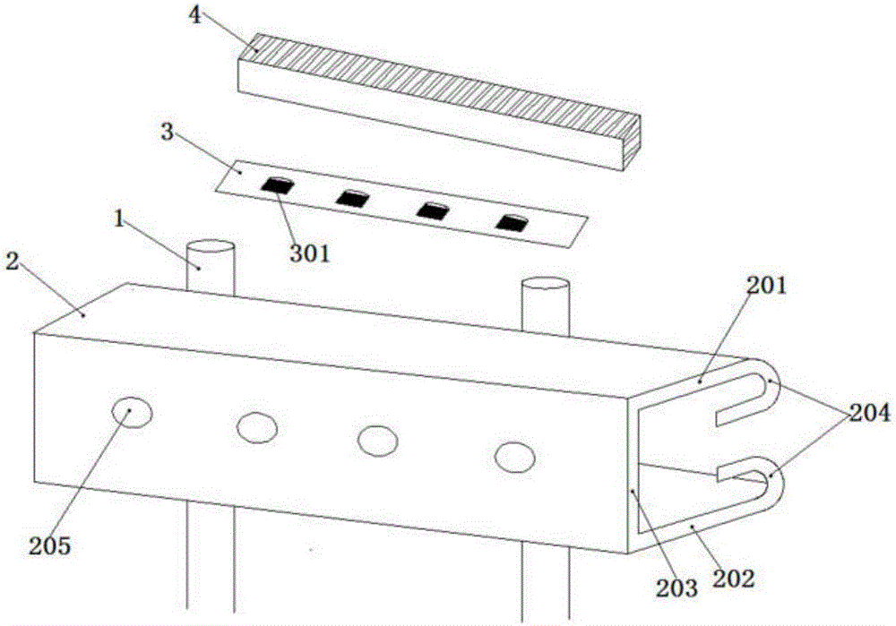
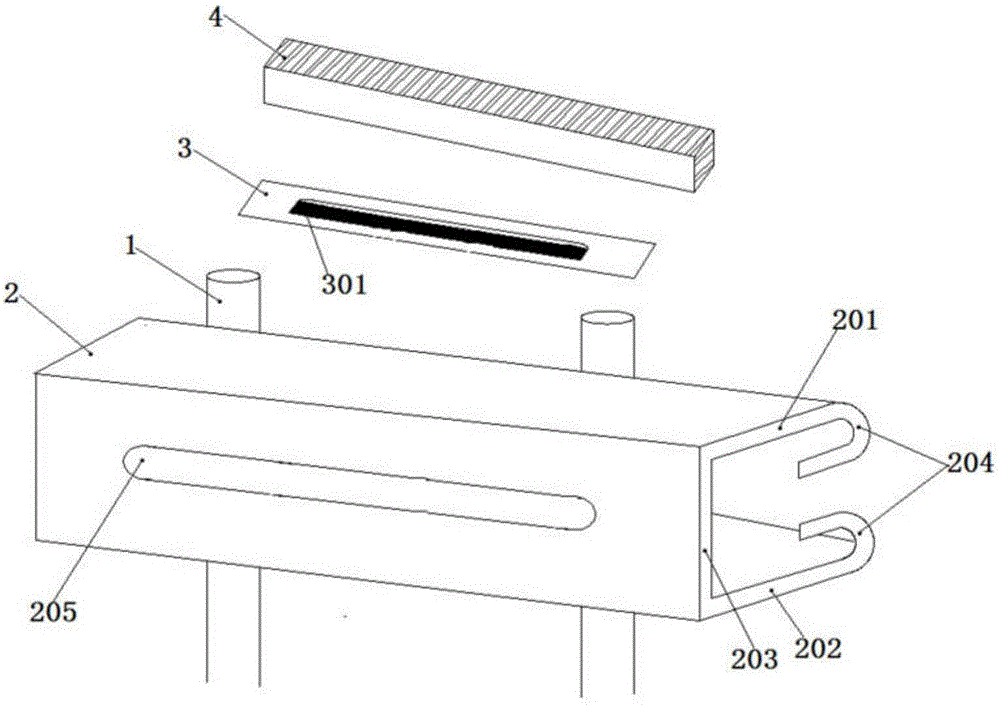
[0093] Such as figure 1 As shown, the guardrail structure in the first embodiment provided by the present invention includes a pillar 1, a guardrail body 2, a lamp assembly 3, and the guardrail body 2 is laterally fixed on a plurality of pillars 1 arranged at intervals. The guardrail body 2 includes a horizontal top plate 201, a horizontal bottom plate 202 and a vertical side plate 203. The other ends of the horizontal top plate 201 and the horizontal bottom plate 202 relative to the vertical side plate 203 are both bent toward the square groove cavity to form a U-shaped end 204.

[0094] The guardrail body 2 constitutes an energy absorbing part, the energy absorbing part is a non-elastic deformation buffer structure, and is a plate body. The plate body is bent and bent to form a groove with an opening toward the outside of the lane, between the upper and lower notches of the groove After relatively curved, it extends toward the inner side of the lane to form an end; the lamp ins...

Embodiment approach

[0100] In the embodiment of the present invention, as a first implementation, the light trough 205 is arranged on the guardrail body 2 in a horizontal linear shape. Specifically, according to the actual installation method of the guardrail body 2, it can be installed on the horizontal top plate 201, A light trough 205 is provided in any one of the horizontal bottom plate 202 and the vertical side plate 203. In this embodiment, the LED light sources 301 will be arranged in a line shape, so that the light is linear. This embodiment includes, but is not limited to: (1) A plurality of light slots 205 are separately arranged on the horizontal top plate 201, the horizontal bottom plate 202 or the vertical side plate 203 of the guardrail body 2 along the transverse direction, and the multiple light slots 205 are arranged in a horizontal direction. Distributed in one or more rows; (2) According to the required luminous intensity, at least two of the horizontal top plate 201, the horizon...

no. 2 example

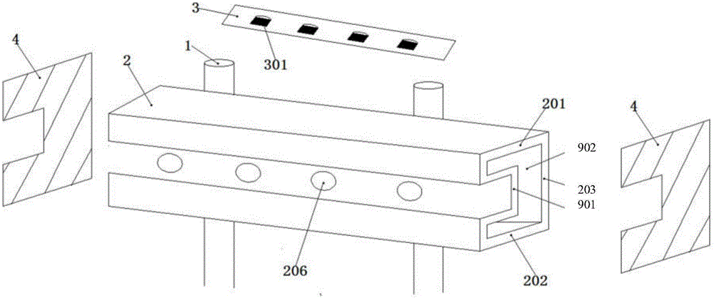
[0102] Such as image 3 As shown, the guardrail structure in the second embodiment provided by the present invention includes a pillar 1, a guardrail body 2, a lamp assembly 3, and the guardrail body 2 is laterally fixed on a plurality of pillars 1 arranged at intervals. The guardrail body 2 includes a horizontal top plate 201, a horizontal bottom plate 202, a vertical side plate 203 and a hat-shaped side plate 901.

[0103] The guardrail body 2 constitutes an energy absorbing part, the energy absorbing part is a non-elastic deformation buffer structure, at least a part of the energy absorbing part is located inside the lamp installation surface in the direction of the inner and outer sides of the lane; the guardrail body is a tube body; The cross-sectional profile is a concave figure; the lamp installation surface has a lamp slot notch; the maximum width of the energy absorbing part in the inner and outer directions of the lane is distributed at a different height position than t...


PUM


Abstract

The invention provides a guardrail structure and a guardrail lamp. The guardrail structure comprises a profile guardrail body, wherein the guardrail body comprises an energy absorption part; the energy absorption part is provided with a lamp installation surface and is of a non-elastic deformation buffer structure; at least one part of the energy absorption part and the lamp installation surface are located at different positions in the inner and outer side direction of a lane; and relatively to the lamp installation surface, at least one part of the energy absorption part is relatively easy to deform. The non-elastic deformation buffer structure is adopted as the energy absorption part and the impact energy can be fully absorbed, so that the protection area is expanded and the impact resistance is improved. One part of the guardrail body has attributes which are easier to deform relative to the other part, and the lamp installation surface can be designed at the part which is not easy to deform, thereby avoiding or reducing fragments generated by impact of lamps; and at least one part of energy absorption part is located at the inner side of the lamp installation surface in the inner and outer side direction of the lane and the part which is firstly struck absorbs relatively large instantaneous impact force shock, thereby reducing the impact to the lamps.

Description

Technical field [0001] The invention relates to the field of road safety facilities, in particular to a guardrail structure and a guardrail lamp. Background technique [0002] In order to ensure the safe driving of vehicles on highways and bridges, anti-collision barriers are usually installed on both sides of roads and bridges such as urban roads, expressways, provincial highways, interchanges, and entrance and exit ramps. The guardrail structure usually includes a guardrail body and a pillar, wherein the guardrail body is fixed laterally between a plurality of pillars arranged at intervals. As the night light is dark, it is easy to cause traffic accidents and often break the guardrail. Therefore, in order to avoid such problems, it is very necessary to provide an illuminated guardrail. [0003] The prior art solves the above problems by installing lighting fixtures on the guardrail, specifically by defining the structure of the guardrail body to be a round tube or oval tube shap...

Claims


Application Information

Patent Timeline
Patent Type & Authority Applications(China)
IPC IPC(8): E01F15/04E01F9/669E01F9/615F21S8/00F21V19/00F21W111/08F21Y115/10
CPCF21S8/00F21V19/00E01F15/04F21W2111/08
Inventor 王鹰华朱国立吴继业姜佩华
Owner SHANGHAI SANSI ELECTRONICS ENG
Why Eureka
Try Eureka