Composite material plate and metal plate lap joint energy absorption device
A composite material board and energy-absorbing device technology, applied in springs, shock absorbers, spring/shock absorbers, etc., can solve problems such as insufficient use of structural materials, low energy absorption efficiency, and heavy weight of energy-absorbing structures
- Summary
- Abstract
- Description
- Claims
- Application Information
AI Technical Summary
Problems solved by technology
Method used
Image
Examples
Embodiment 1
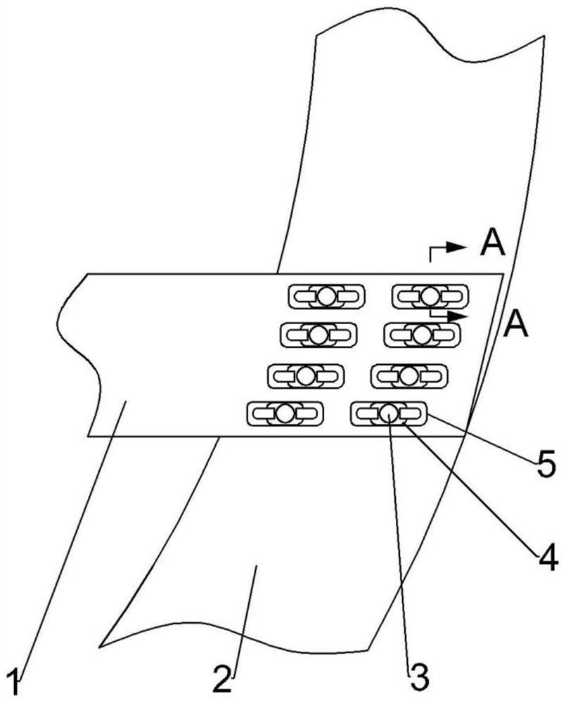
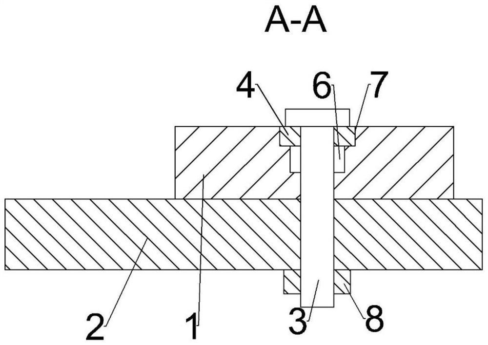
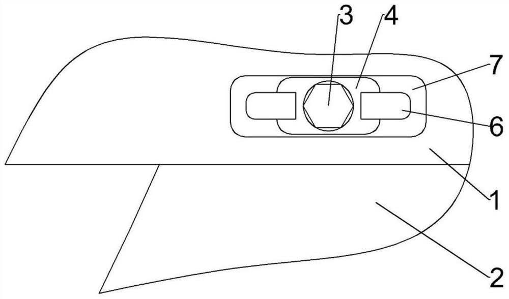
[0033] refer to Figure 1-3 , the present invention provides a composite material plate and a metal plate overlap energy-absorbing device, including a first plate 1 and a second plate 2, the first plate 1 is located above the second plate 2, the first plate 1 and the second plate 2 are connected by fastening components;
[0034] The first plate 1 is provided with a stepped groove 5, the fastening component is located in the stepped groove 5, the bottom of the stepped groove 5 is used to buffer the movement of the fastening component, and the fastening component runs through the second plate 2 and In the through hole at the bottom of the stepped groove 5, there is a gap between the fastening component and the inner side wall of the stepped groove 5 and the through hole; a gasket 4 is arranged between the head of the fastening component and the stepped groove 5 .
[0035] When the aircraft lands normally, the energy-absorbing device is used as a load-bearing structure, and the...
Embodiment 2
[0049] refer to Figure 4-7 The difference between the energy absorbing device of this embodiment and the first embodiment is only that the second plate 2 is provided with a sliding long groove 9, the direction of the sliding long groove 9 is perpendicular to the direction of the stepped groove 5, and the bolt 3 penetrates the stepped groove. The intersection of the groove 5 and the sliding slot 9, the energy-absorbing boxes are arranged on both sides of the first plate 1, the energy-absorbing boxes are fixedly connected between the first plate 1 and the second plate 2, and the energy-absorbing boxes have a square structure.
[0050] The solution is further optimized. The energy-absorbing box includes a fixed wall 10 of the energy-absorbing box that is fixedly connected to the second plate 2. The inner wall of the fixed wall 10 of the energy-absorbing box is fixedly connected with two crushing blocks 11, and between the two crushing blocks 11 are arranged There is a gap, a cur...
Embodiment 3
[0056] refer to Figure 8-11 The difference between the stepped groove 5 of this embodiment and the first embodiment is only that the stepped groove 5 is provided with a second groove 7 and a third groove 17, and the third groove 17 is located in the second groove 7 Below, the distance between the inner long side walls of the third groove 17 is smaller than the major diameter of the bolt 3, the third groove 17 is provided with a bolt hole 18, and the bolt 3 passes through the bolt hole 18 and the second plate 2 and the bolt hole 18. Nut 8 is screwed.
[0057] The working process of this embodiment is as follows:
[0058] When a collision occurs, the second plate 2 drives the bolts 3 to move relative to the first plate 1, and the bolts 3 move in the third grooves 17. Since the distance between the third grooves 17 is smaller than the major diameter of the bolts 3, even if The moving direction of the bolt 3 is the same as that of the stepped groove 5, and the bolt 3 can be mor...
PUM
 Abstract
Description
Claims
Application Information
 - R&D
- Intellectual Property
- Life Sciences
- Materials
- Tech Scout
- Unparalleled Data Quality
- Higher Quality Content
- 60% Fewer Hallucinations
Browse by: Latest US Patents, China's latest patents, Technical Efficacy Thesaurus, Application Domain, Technology Topic, Popular Technical Reports.
© 2025 PatSnap. All rights reserved.Legal|Privacy policy|Modern Slavery Act Transparency Statement|Sitemap|About US| Contact US: help@patsnap.com


