Spring pressure plan based on engine rotation speed

A technology of engine speed and engine, applied in the direction of engine components, machines/engines, non-mechanically actuated valves, etc., to reduce fuel consumption, reduce noise, and prolong service life

Inactive Publication Date: 2017-06-13
NANAN GAOJIE ELECTRONICS TECH
View PDF0 Cites 0 Cited by
  • Summary
  • Abstract
  • Description
  • Claims
  • Application Information

AI Technical Summary

Problems solved by technology

[0006] The invention proposes a valve adjustment system and method, which solves the problem of the same valve spring pressure at different engine speeds in the prior art

Method used


Image

  • Spring pressure plan based on engine rotation speed
  • Spring pressure plan based on engine rotation speed
  • Spring pressure plan based on engine rotation speed

Examples


Embodiment Construction

[0042] The following will clearly and completely describe the technical solutions in the embodiments of the present invention with reference to the accompanying drawings in the embodiments of the present invention. Obviously, the described embodiments are only some, not all, embodiments of the present invention. Based on the embodiments of the present invention, all other embodiments obtained by persons of ordinary skill in the art without creative efforts fall within the protection scope of the present invention.

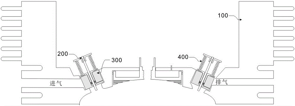
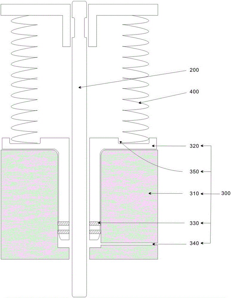
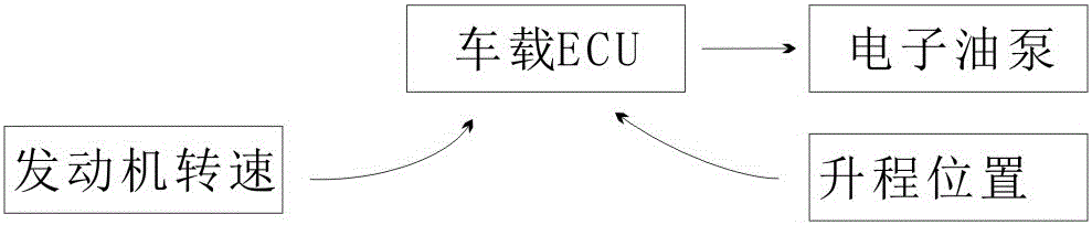
[0043] A method for controlling engine valve springs, comprising: adjusting pressure to the valve springs 400 based on engine speed, adjusting the pressure to the valve springs 400 includes adjusting an electrical control coupled to an oil pump. The valve spring 200 is the inner spring of the valve 200 or the outer spring of the valve 200 ; or, the valve spring 400 is the inner spring of the valve 200 and the outer spring of the valve 200 .

[0044] Among them, suc...


PUM


Abstract

The invention provides a system and method for controlling an engine valve spring. The method comprises the steps that the pressure of the valve spring is adjusted on the basis of the engine rotation speed, valve spring pressure adjustment comprises adjustment on electric control connected with an oil pump, the oil pump controls the lift of a base, and lift control is conducted on the basis of the oil supply amount of the oil pump to the base. For example, when the engine rotation speed is changed to 2,000 r/min from the idle speed which is 700 r/min, a piston is pushed through oil pumping of the oil pump to be pushed to move upwards from the start point, the valve spring pressure is increased, and the valve reset speed becomes high.

Description

technical field [0001] The invention relates to a gasoline engine, in particular to an adjustment method capable of changing the valve spring pressure according to the engine speed. Background technique [0002] The valve spring of the engine is the only part that guarantees the valve reset. If the valve spring force is too large, it will seriously damage the wear of the parts of the valve train. If the valve spring force is too small, the valve reset will lag behind, causing the valve and the power piston to collide. [0003] The return force of the valve spring is set according to the maximum speed of the engine to ensure the high-speed operation of the engine. However, the pressure of the valve spring at the highest speed is relatively large, which will inevitably affect the torque of the engine at low speeds. [0004] In order to achieve the reset speed of the valve in some high-speed engines, the valve spring adopts a double spring design, one inner spring and one outer...

Claims


Application Information

Patent Timeline
Patent Type & Authority Applications(China)
IPC IPC(8): F01L3/10F01L9/02F01L9/10
CPCF01L3/10F01L2810/04F01L9/10
Inventor 庄景阳
Owner NANAN GAOJIE ELECTRONICS TECH
Why Eureka
Try Eureka