Visual precise measurement system and method for micro parts

A technology for tiny parts and precise measurement, used in optical testing for flaws/defects, etc., to ensure stability, improve productivity, and reduce work efficiency

Inactive Publication Date: 2017-06-13
NORTH CHINA UNIVERSITY OF TECHNOLOGY
View PDF3 Cites 2 Cited by
  • Summary
  • Abstract
  • Description
  • Claims
  • Application Information

AI Technical Summary

Problems solved by technology

[0005] Although there are many measurement methods and systems using computer vision detection technology in the prior art, continuous improvements are still needed in terms of measurement time, measurement cost, and measurement accuracy.

Method used


Image

  • Visual precise measurement system and method for micro parts
  • Visual precise measurement system and method for micro parts
  • Visual precise measurement system and method for micro parts

Examples


Embodiment Construction

[0034] Exemplary embodiments of the present invention will be described in more detail below with reference to the accompanying drawings. Although exemplary embodiments of the present invention are shown in the drawings, it should be understood that the invention may be embodied in various forms and should not be limited to the embodiments set forth herein. Rather, these embodiments are provided for more thorough understanding of the present invention and to fully convey the scope of the present invention to those skilled in the art.

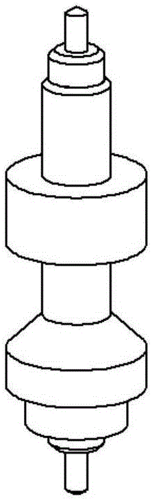
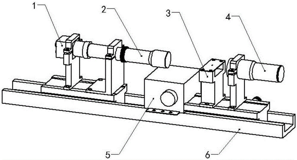
[0035] figure 1 is a diagram of a watch escapement pinion as an example minute part. Such as figure 1 The escapement pinion in the shown mechanical clock is only a typical representative of many small parts, and it is only for the purpose of illustration. The measurement system and method proposed by the present invention will be described below in conjunction with the escapement pinion. However, the measurement system and method proposed by ...


PUM


Abstract

The invention discloses a visual precise measurement system and method for micro parts. The measurement system comprises an image acquiring device and a feature analysis and parameter measurement device, the image acquiring device is used for acquiring backlight images of the micro parts to be measured as input images and outputting the same and comprises a camera, a telecentric lens, an object state and a parallel light source which are sequentially arranged on a guide rail and adjustable in position, the parallel light source is used for irradiating the micro parts to be measured on the object stage, and the camera acquires the backlight images of the micro parts to be measured as the input images through the telecentric lens and outputting the input images; the feature analysis and parameter measurement device is connected with the image acquiring device and used for receiving the input images, analyzing and extracting features of the input images and acquiring and outputting measurement parameters. The visual precise measurement system can quickly and accurately realize parameter measurement of the micro parts like an escape gear shaft.

Description

technical field [0001] The invention relates to the field of tiny parts detection, in particular to a visual precision measurement system and method for tiny parts. Background technique [0002] The escapement mechanism is the core of modern mechanical clocks and watches. The original escapement mechanism was born in the 15th century, and then gradually evolved into various forms today. More specifically, the escapement mechanism is a switching device that transmits mechanical energy. This switching device is controlled by the timing reference and switches the main transmission chain of the clock at a certain frequency, so that the mechanical clock stops alternately and at a certain average speed. Turn to indicate the exact time. The function of the escapement mechanism can be understood from two aspects: escapement, to lock (capture) the movement of the main drive, at this time, the main drive chain of the watch is locked; ) The main transmission chain moves, and at the s...

Claims


Application Information

Patent Timeline
Patent Type & Authority Applications(China)
IPC IPC(8): G01N21/95
CPCG01N21/95
Inventor 张从鹏侯波马岩曹文政李小龙
Owner NORTH CHINA UNIVERSITY OF TECHNOLOGY
Why Eureka
Try Eureka